Non-contact condensation detecting method and non-contact condensation detecting apparatus
a detection method and non-contact technology, applied in the direction of measurement devices, instruments, materials moisture content, etc., can solve the problems of affecting the measurement of the temperature sensor located downstream, inability to perform precise measurements, and excessive heat conducted to the inner walls of the flow path, so as to accurately predict dew condensation and transpiration. , to achieve the effect of efficiently preventing dew condensation and accurate prediction
- Summary
- Abstract
- Description
- Claims
- Application Information
AI Technical Summary
Benefits of technology
Problems solved by technology
Method used
Image
Examples
first embodiment
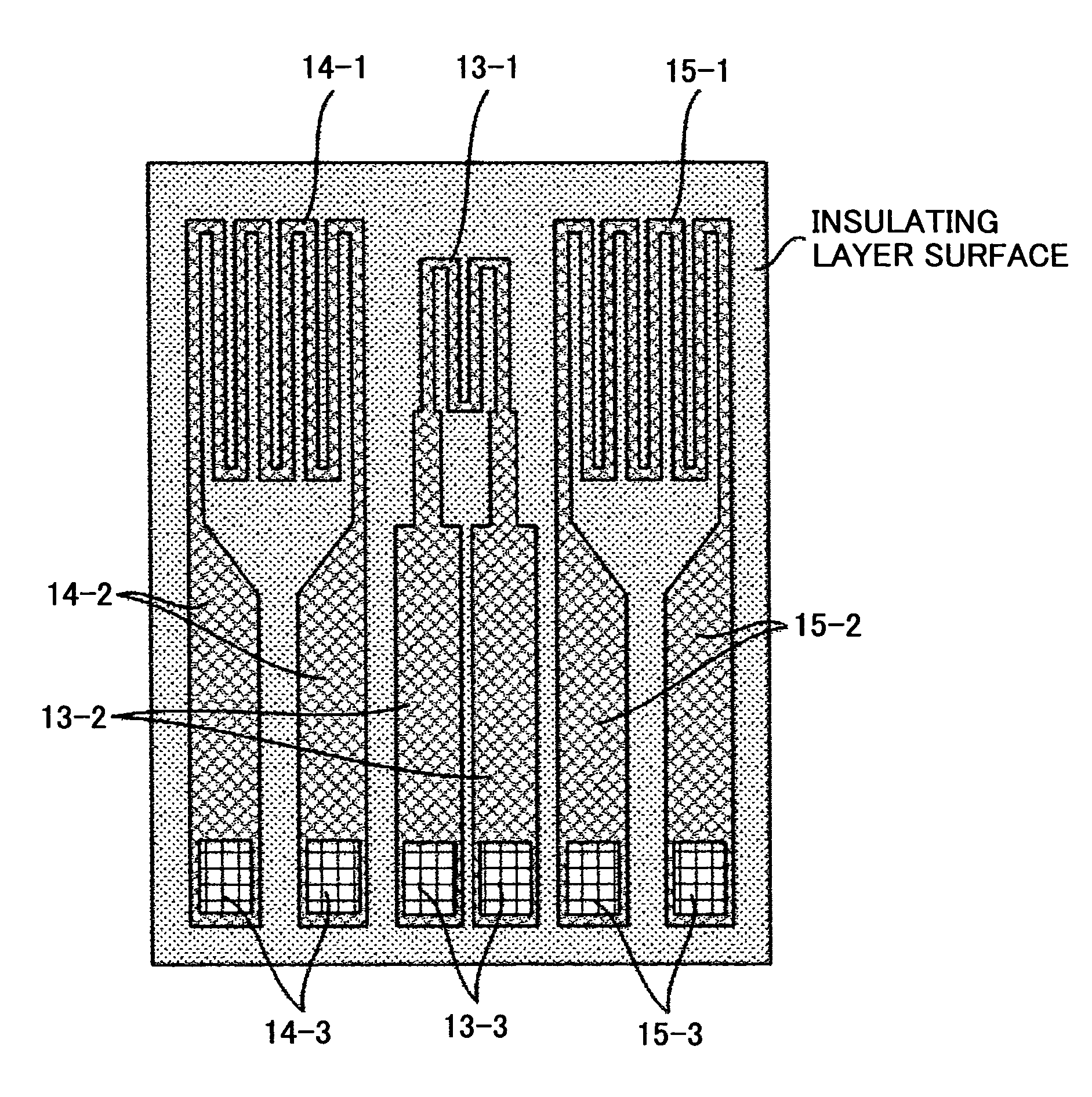
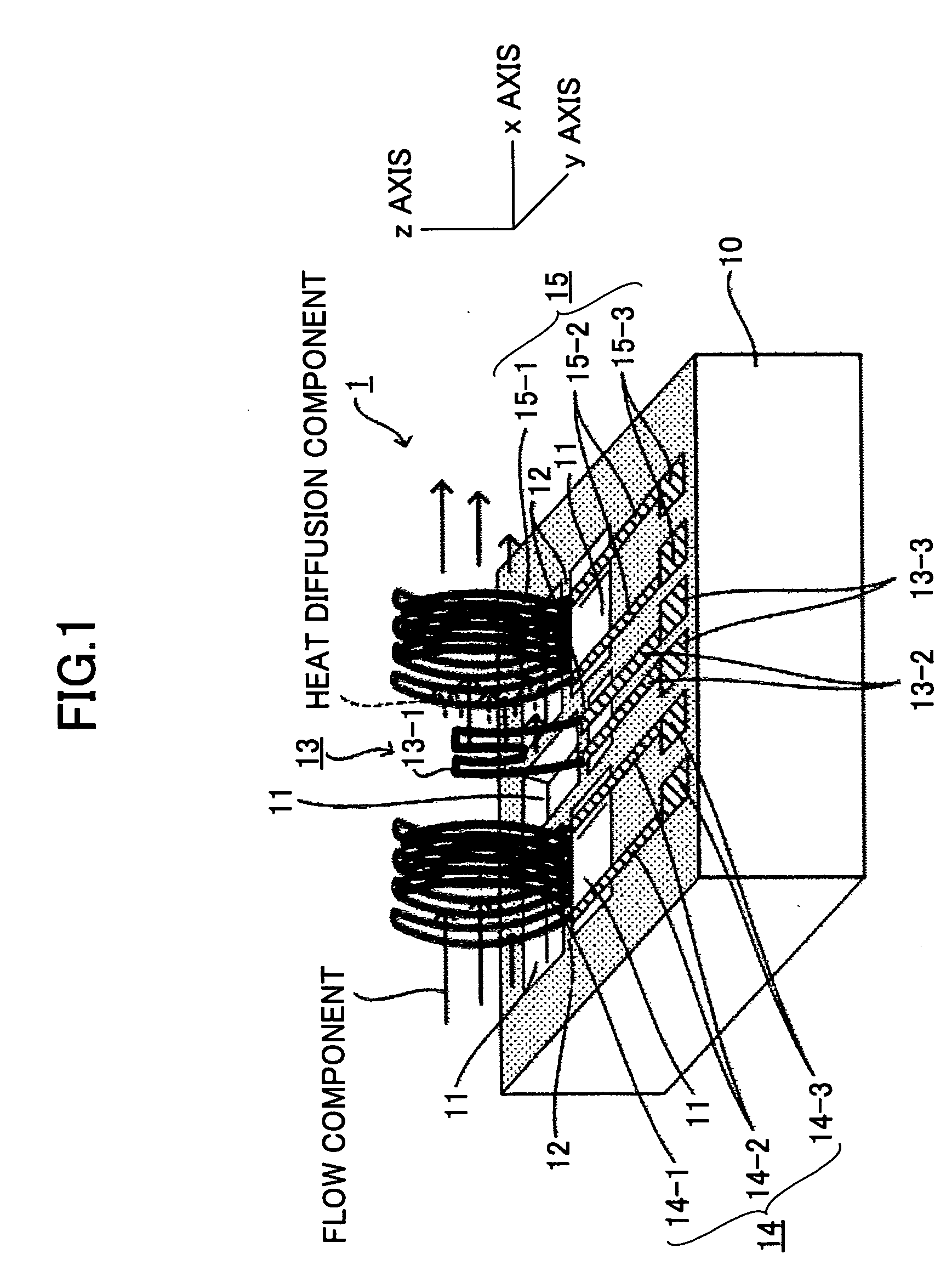
[0111]FIG. 1 is a perspective view of a configuration of a detector element 1 according to the present invention. The detector element 1 includes a substrate 10, bridges 12 disposed across voids 11 in the substrate 10, a heating unit 13, and two temperature sensors 14, 15 disposed on the bridges 12, respectively. The two temperature sensors 14, 15 are disposed in parallel one on each side of the heating unit 13. The temperature sensors 14, 15 include temperature sensor electrodes 14-1, 15-1, respectively, which are shaped like the curved surface of a pipe, and are arranged facing each other. The heating unit 13 includes a heat generating electrode 13-1 connected to power supply leads 13-2. An electrode pad 13-3 is connected to each power supply lead 13-2. The heating unit 13 generates Joule heat using power supplied from the electrode pads 13-3. Further, detection leads 14-2, 15-2 are connected to the ends of the temperature sensor electrodes 14-1, 15-1 of the temperature sensors 14...
third embodiment
[0121] A method of fabricating the detector element 3 is described with reference to FIGS. 9 and 10. FIGS. 9 and 10A are plan views, and FIG. 10B is a cross-sectional view taken along line C-C′ of FIG. 10B. Elements corresponding to those in FIG. 1 are denoted by the same reference numbers.
[0122] As shown in FIG. 9, the heating unit 13 overlaps the temperature sensors 14, 15, and therefore, the heating unit 13 is to be formed by using a sacrifice layer, in a subsequent step after the temperature sensors 14, 15 are formed. First, patterns made of conductive material films are formed on the substrate 10 for the temperature sensor electrodes 14-1, 15-1, the detection leads 14-2, 15-2, and the electrode pads 14-3, 15-3 of the temperature sensors 14, 15, respectively. A metal material having a high resistance temperature coefficient such as Pt, W is used for the heating unit 13 and the temperature sensors 14, 15. Next, patterns made of, for example, Ni, are formed in areas to become the...
fifth embodiment
[0126] A method of fabricating the detector element 5 is described with reference to FIGS. 14, 15A, and 15B. FIG. 14 and FIG. 15A are plan views, and FIG. 15B is a cross-sectional view taken along line F-F′ of FIG. 15A. As shown in FIG. 14, patterns made of conductive material films are formed on the substrate 10 for the temperature sensor electrode 50-1 of the temperature sensor 50, the detection leads 50-2, the heat generating electrode 51-1 and the power supply leads 51-2 of the heating unit 51, and the electrode pads 50-3, 51-3. As shown in FIGS. 15A, 15B, the insulating layer in the area corresponding to the temperature sensor electrode 50-1 of the temperature sensor 50 and the heat generating electrode 51-1 of the heating unit 51 on the substrate 10 are removed by etching. The temperature sensor 50 and the heating unit 51 are partly detached from the lower layer, forming cantilevered structures. The temperature sensor 50 and the heating unit 51 then form curved surfaces due t...
PUM
 Abstract
Description
Claims
Application Information
 - R&D
- Intellectual Property
- Life Sciences
- Materials
- Tech Scout
- Unparalleled Data Quality
- Higher Quality Content
- 60% Fewer Hallucinations
Browse by: Latest US Patents, China's latest patents, Technical Efficacy Thesaurus, Application Domain, Technology Topic, Popular Technical Reports.
© 2025 PatSnap. All rights reserved.Legal|Privacy policy|Modern Slavery Act Transparency Statement|Sitemap|About US| Contact US: help@patsnap.com


