
Method for testing a mass flow rate meter

Inactive Publication Date: 2007-05-24
KRONE GMBH
View PDF5 Cites 41 Cited by
  • Summary
  • Abstract
  • Description
  • Claims
  • Application Information

AI Technical Summary

Benefits of technology

[0008] Based on the method described above, this task is thereby solved in that the osc

Problems solved by technology

A difficulty with Coriolis mass flow rate meters is that, when they are used, over time, changes can occur which lead to a loss of measuring accuracy.
However, a problem with this known method is that the density of the flowing medium must be known.

Method used


Image

  • Method for testing a mass flow rate meter
  • Method for testing a mass flow rate meter
  • Method for testing a mass flow rate meter

Examples


Embodiment Construction

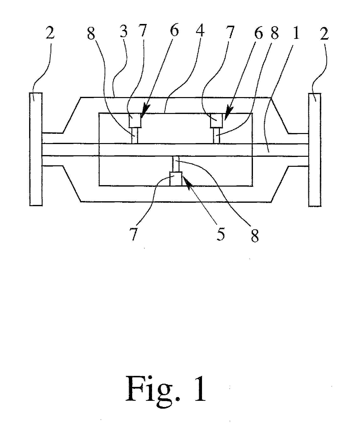
[0022] During manufacturing of a Coriolis mass flow rate meter, various requirements are placed on construction tolerances, material properties and other manufacturing parameters. However, even when all of these requirements are fulfilled, the possibility cannot be precluded that the mass flow rate meter finally fails to meet the demands or cannot be used at all, and therefore, has to be reworked. In conjunction with the manufacturing parameters, the smallest deviations may lead to a device of this type, which no longer has sufficient measuring accuracy.

[0023] Furthermore, it is also possible that factors or other matters whose importance or effects cannot be calculated could occur during measuring operation of a Coriolis mass flow rate meter, influencing the operation of the mass flow rate meter. In this way, for example, the calibration condition of the Coriolis mass flow rate meter could be lost so that the measuring results obtained are no longer reliable.

[0024] With the prese...


PUM


Abstract

A method of testing a mass flow rate meter functioning on the Coriolis principle, in which an apparatus of the mass flow rate meter is subjected to a predetermined oscillation excitation and the associated oscillation response is recorded. Then the recorded oscillation response is compared with a previously recorded oscillation response. Testing of the Coriolis mass flow rate meter with regard, for example, to error tolerances in the manufacturing or with regard to a calibration condition is thereby enabled.

Description

BACKGROUND OF THE INVENTION [0001] 1. Field of the Invention [0002] The invention relates to a method for testing a mass flow rate meter which functions according to the Coriolis principle, wherein an apparatus of the mass flow rate meter is subjected to a predetermined oscillation excitation and the associated oscillation response is recorded. [0003] 2. Description of Related Art [0004] Coriolis mass flow rate meters generally have a measuring tube or a plurality of measuring tubes which, during operation, are excited into oscillation. A medium whose mass flow rate is to be determined and which flows through the measuring tube or tubes is thereby subjected to a Coriolis force, which leads to a change in the oscillation displacement relative to the oscillation excitation of the measuring tube or tubes. This change is used, for example, in the form of a phase difference in an oscillating measuring tube at sites spaced from each other for direct determination of the mass flow rate. [0...

Claims


Application Information

Patent Timeline
IPC IPC(8): G01F1/84
CPCG01F1/8413G01F1/8427G01F1/849G01F25/0007G01F25/10
Inventor BAKER, ROGERWANG, TAOHUSSAIN, YOUSIFWOODHOUSE, JIM
Owner KRONE GMBH
Learn More