Subdivision surface-based geometric modeling system
What is AI technical title?
AI technical title is built by Patsnap AI team. It summarizes the technical point description of the patent document.
a geometric modeling and subdivision surface technology, applied in the field of images, can solve the problem of few suitable methods for dealing with precision/error control of subdivision surfaces
Inactive Publication Date: 2007-04-03
UNIV OF KENTUCKY RES FOUND
View PDF12 Cites 30 Cited by
Summary
Abstract
Description
Claims
Application Information
AI Technical Summary
This helps you quickly interpret patents by identifying the three key elements:
Problems solved by technology
Method used
Benefits of technology
Benefits of technology
[0007]In accordance with a first aspect of the invention, a method for modeling or representing a surface or shape having an arbitrary topology which may be represented by a control mesh comprising at least one discrete Catmull-Clark Subdivision Surface (CCSS) patch defined by a set of control points is provided, comprising the steps of computing a subdivision depth determining the number of recursive subdivisions which may be performed on the control mesh to generate a plurality of
Problems solved by technology
However, there are presently few suitable methods for dealing with precision / error control in subdivision surfaces, and in “smart” tessellation of subdivision surfaces.
Method used
Image
Click on the blue label to locate the original text in one second.
Reading with bidirectional positioning of images and text.
Examples
example 1
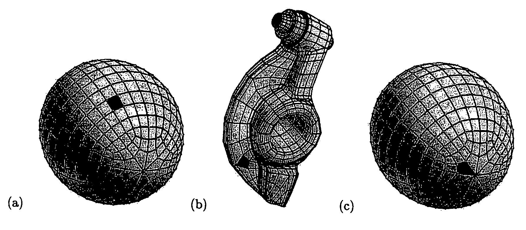
[0091]Referring to FIG. 6, distance and subdivision depth computation for a CCSS patch was calculated for several surfaces. The distances between the faces of the control meshes and the corresponding limit surface patches for each mesh face were 0.034 (FIG. 6a), 0.25 (FIG. 6b), and 0.15 (FIG. 6c). For an error tolerance of 0.01, the subdivision depths computed for each mesh face was 1 (FIG. 6a), 24 (FIG. 6b), and 22 (FIG. 6c). The calculated subdivision depths for the mesh faces shown in FIGS. 6b and 6c were greater because each surface has an extraordinary vertex. For the mesh face shown in FIG. 6b, subdivision depths for error tolerances 0.25, 0.2, 0.1, 0.01, 0.001, and 0.0001 were 1, 3, 9, 24, 40, and 56, respectively.
example 2
[0092]FIGS. 7, 8, and 9 compare conventional uniform Catmull-Clark subdivision with the adaptive subdivision method of the present invention. Referring to FIG. 7 showing a rocker arm, uniform Catmull-Clark subdivision resulted in 22,656 vertices, 45,312 edges, and 22,656 faces (FIG. 7c) for an error of 0.25. In contrast, the adaptive subdivision method of the present invention (FIG. 7d) generated 2,706 vertices, 5,412 edges, and 2,706 faces, i.e. only 3 / 25 of the total vertices, edges, and faces required for conventional Catmull-Clark subdivision. Lowering the error tolerance to 0.2 resulted in a maximum subdivision depth of 4. In this latter case, uniform Catmull-Clark subdivision generated 362,496 vertices, 724,992 edges, and 362,496 faces. In comparison, the label-driven adaptive subdivision method of this invention generated only 9,022 vertices, 18,044 edges, and 9,022 faces, or a 40× improvement on the total number of vertices, faces, and edges.
PUM
Abstract
A method for surface modeling of images to produce realistic images or to provide simulations with accurate surface information is provided. More particularly, the present invention relates to a new subdivision depth computation technique and to an improved label-driven adaptive subdivision technique for use in Catmull-Clark subdivision surface modeling systems. The method comprises computing a subdivision depth to determine the number of recursive subdivisions which may be performed on a control mesh to generate a plurality of finer mesh elements while preserving a predetermined error tolerance, and using the computed subdivision depth to construct an adaptively refined mesh that is substantially similar to the control mesh within the predetermined error tolerance. Limit control surfaces with and without extraordinary vertices may be analysed using the method of the invention. In another aspect, a software program for accomplishing the method of the present invention is provided.
Description
[0001]This application claims the benefit of U.S. Provisional Patent Application Ser. No. 60 / 388,637 filed Jun. 14, 2002. This invention was made with Government support under NSF Grant No. DMI-9912069. The Government may have certain rights in this invention.TECHNICAL FIELD[0002]The present invention relates to the art of surface modeling of images to produce realistic images or to provide simulations with accurate surface information. More particularly, the present invention relates to a new subdivision depth computation technique and to an improved label-driven adaptive subdivision technique for use in Catmull-Clark subdivision surface modeling systems.BACKGROUND OF THE INVENTION[0003]Subdivision surfaces have become popular recently in graphical modeling, animation, and CAD / CAM because of their stability in numerical computation, simplicity in coding, and most importantly their capability in modeling / representing complex shape of arbitrary topology. Given a control mesh and a se...
Claims
Application Information
Patent Timeline
Application Date:The date an application was filed.
Publication Date:The date a patent or application was officially published.
First Publication Date:The earliest publication date of a patent with the same application number.
Issue Date:Publication date of the patent grant document.
PCT Entry Date:The Entry date of PCT National Phase.
Estimated Expiry Date:The statutory expiry date of a patent right according to the Patent Law, and it is the longest term of protection that the patent right can achieve without the termination of the patent right due to other reasons(Term extension factor has been taken into account ).
Invalid Date:Actual expiry date is based on effective date or publication date of legal transaction data of invalid patent.

