Brushless motor

a brushless motor and annular step technology, applied in the direction of dynamo-electric machines, magnetic circuit shapes/forms/construction, structural associations, etc., can solve the problems of excessive force directed in the radial direction, drive up the price of brushless motors, and ineffective facilitation of manufacturing of brushless motors

Inactive Publication Date: 2007-05-24
NIDEC CORP
View PDF8 Cites 7 Cited by
  • Summary
  • Abstract
  • Description
  • Claims
  • Application Information

AI Technical Summary

Benefits of technology

[0007] In order to overcome the problems described above, preferred embodiments of the present invention provide a reliable and durable brushless motor. In addition, manufacturing of the brushless motor is effectively facilitated.
[0008] According to a preferred embodiment of the present invention, the protruding portion is formed on the shaft by a rolling process. According to another preferred embodiment of the present invention, a plurality of protruding portions may be circumferentially arranged on the shaft in an equally circumferentially spaced manner. The protruding portion protrudes radially outwardly from about 3% to about 5% of an outer diameter of a portion of the shaft where the ball bearing is attached. By virtue of this configuration, the manufacturing process of the motor is facilitated, and the durability of the shaft is preferably maintained. Additionally, axial positioning of the ball bearing is facilitated.
[0009] According to another preferred embodiment of the present invention, the gear is provided on an axial end portion of the shaft. The gear is arranged axially outside of the motor, and the protruding portion is provided axially between the gear and the ball bearing. Upon providing the gear on the end portion of the shaft, a force in the radial direction is applied to the shaft and stress is concentrated on a portion near where the protruding portion is arranged. In the present preferred embodiment of the present invention, the protruding portion is formed by rolling and the durability of the portion of the shaft is preferably maintained.
[0010] According to another preferred embodiment of the present invention, a plurality of ball bearings are arranged in an axially spaced manner, and at least one ball bearing arranged near the gear is secured to the shaft by press-fitting. By virtue of this configuration, a reliable and durable motor is provided.

Problems solved by technology

However, the conventional method of providing the annular step on the shaft does not meet the demand in terms of a cost for processing the shaft.
Such an additional component (i.e., the annular member) and additional processing procedures drive up the price of the brushless motor.
Especially when a gear which engages with a gear wheel of another device is arranged on a bottom end of the shaft, an excessive force directed in the radial direction is applied to the shaft.
Therefore, as a result of the long duration of driving the brushless motor, the shaft may be damaged.

Method used


Image

  • Brushless motor
  • Brushless motor
  • Brushless motor

Examples


Embodiment Construction

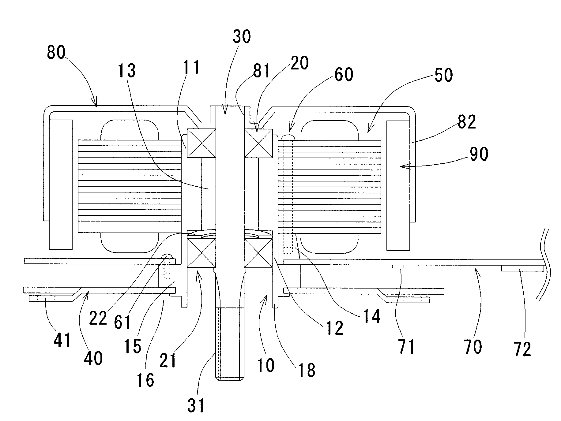
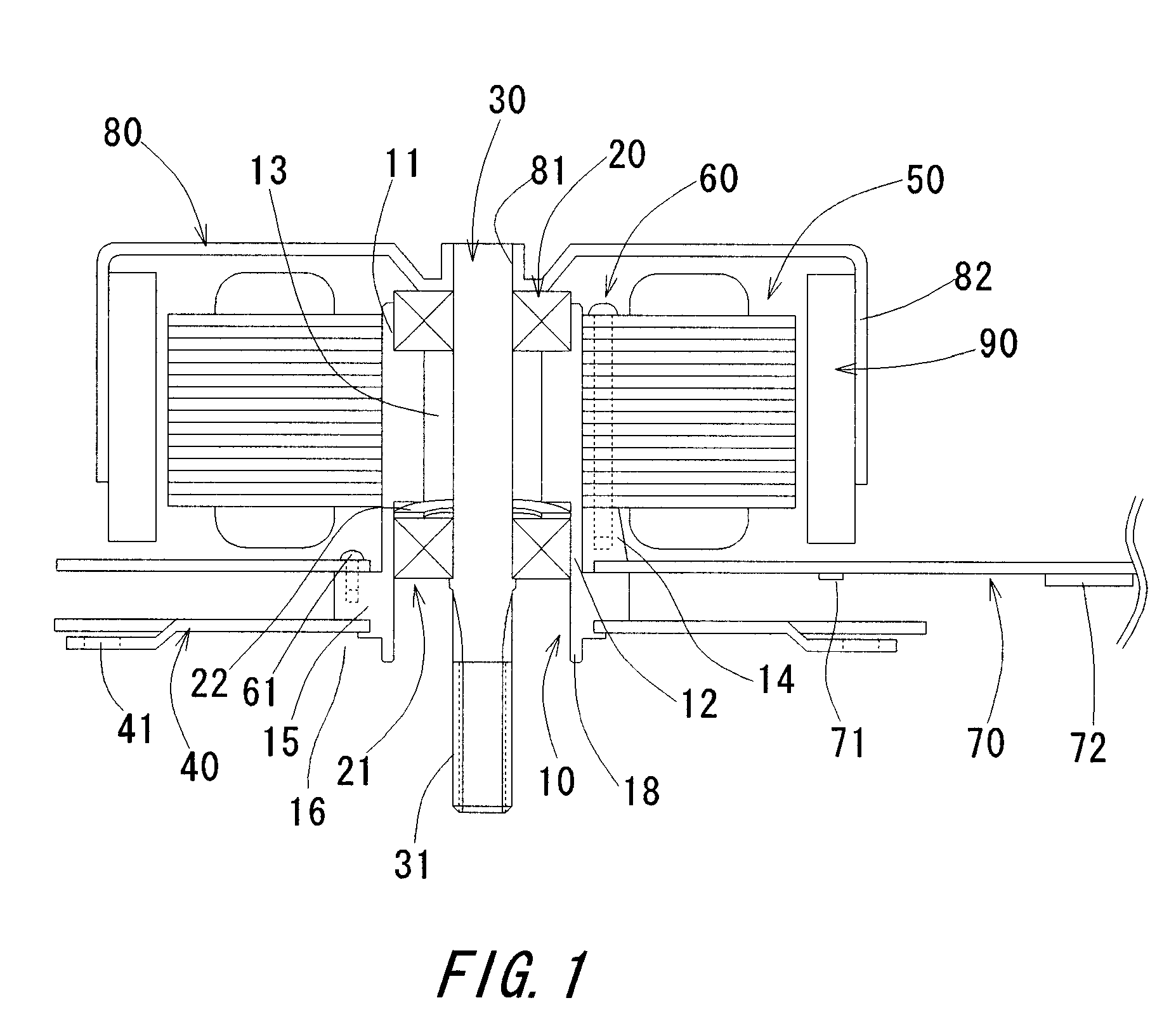
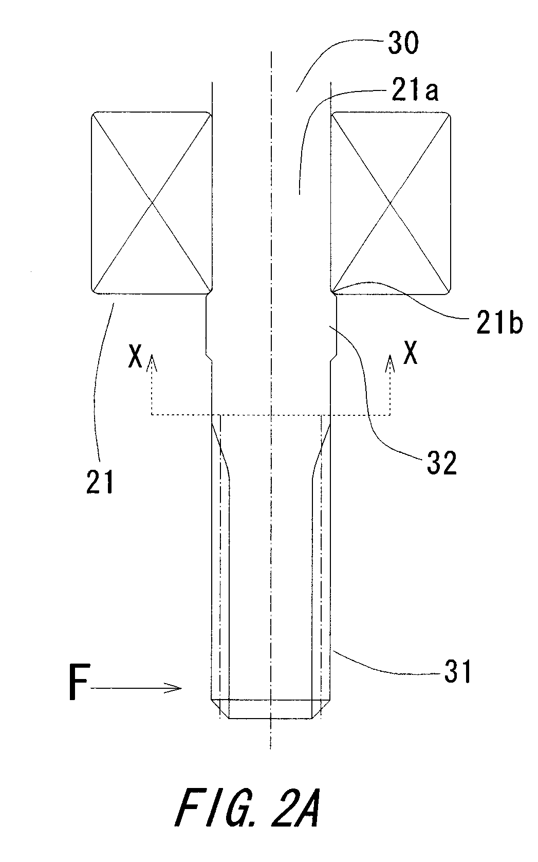
[0018] Referring to FIGS. 1 to 4B, a brushless motor according to preferred embodiments of the present invention will be described in detail. It should be understood that in the explanation of the present invention, when positional relationships among and orientations of the different components are described as being such as top / bottom, up / down or left / right, positional relationships and orientations that are in the drawings are indicated, and positional relationships among and orientations of the components once having been assembled into an actual device are not indicated. Additionally, in the following description, an axial direction indicates a direction parallel to a rotation axis, and a radial direction indicates a direction perpendicular to the rotation axis.

Configuration of the Brushless Motor

[0019] Referring to FIG. 1, the configuration of the brushless motor according to a preferred embodiment of the present invention will be described in detail.

[0020] A bearing holde...


PUM


Abstract

A shaft of a brushless motor includes a protruding portion, and a ball bearing abutting against the protruding portion for axially positioning the ball bearing. The protruding portion is formed by rolling, and a plurality of protruding portions are arranged on the shaft in a circumferentially equally spaced manner. By forming the protruding portions by rolling, durability of the shaft against a force in a radial direction is enhanced, and therefore, it is possible to provide a reliable brushless motor.

Description

BACKGROUND OF THE INVENTION [0001] 1. Field of the Invention [0002] The present invention generally relates to a brushless motor equipped with a roller bearing. [0003] 2. Description of the Related Art [0004] A roller bearing is used for a brushless motor to obtain a highly reliable and durable brushless motor. In such a brushless motor, the roller bearing is axially positioned by abutting against an annular step provided on a shaft of the brushless motor. In another example, the roller bearing is abutted against an annular member arranged on the shaft for axially positioning the roller bearing. It is also known that a plurality of swells each having a doughnut shape are provided on the shaft for axially positioning the roller bearing by abutting the roller bearing against the swells. [0005] Recently, a brushless motor having a competitive price and reliable performance is in demand. However, the conventional method of providing the annular step on the shaft does not meet the demand...

Claims


Application Information

Patent Timeline
Patent Type & Authority Applications(United States)
IPC IPC(8): H02K7/00H02K7/10H02K5/16
CPCH02K5/1735H02K7/003
Inventor SHIMOYAMA, TATSUYAMANO, MASAAKI
Owner NIDEC CORP
Why Eureka
Try Eureka