Radar system

a technology of a radar system and a radar is applied in the field of radar systems, which can solve problems such as error in determination, error in the amount of axis deviation, and error in the azimuth angl

Active Publication Date: 2007-05-24
MITSUBISHI ELECTRIC CORP
View PDF14 Cites 22 Cited by
  • Summary
  • Abstract
  • Description
  • Claims
  • Application Information

AI Technical Summary

Benefits of technology

[0012] According to the radar system of the present invention, there may be obtained such an effect that the appropriate angular precision may be determined by calculating angle error based on a relative speed between reflecting

Problems solved by technology

In such the radar systems described above, the mechanical and electrical precision of the devices causes an azimuth angle error.
In the conventional radar device, differences in the electric properties of the respective antennas cause a receiving intensity error, and as a result, an error occurs in the determination result of the azimuth angle of the reflecting point.
In the another conventional radar device, since the error of the angle sensor causes an error in the transmission angle of the respective beams, an error occurs in

Method used


Image

  • Radar system
  • Radar system
  • Radar system

Examples


first embodiment

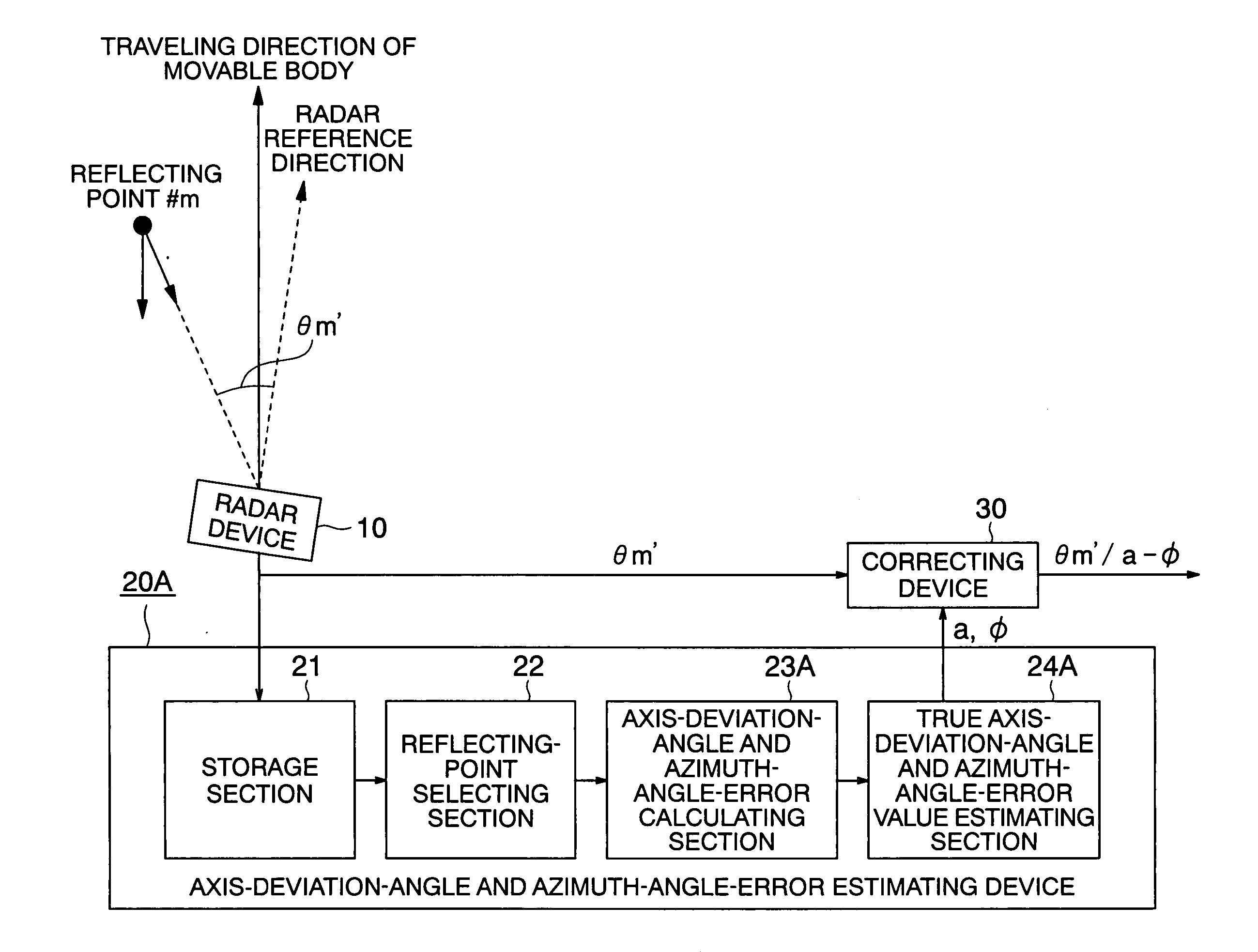
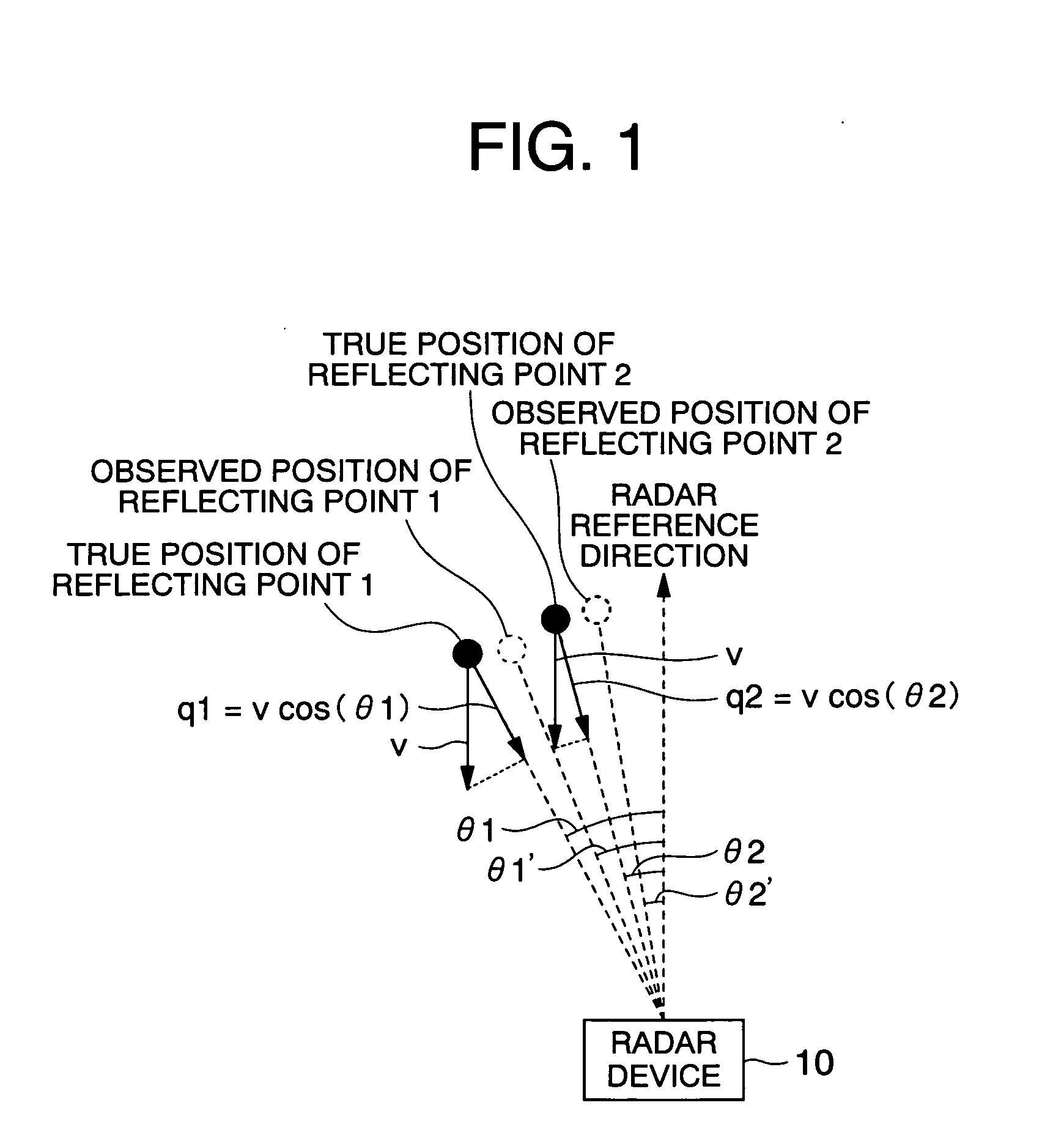
[0019] A radar system according to a first embodiment of the present invention will be described with reference to FIGS. 1 through 3. FIG. 1 is a diagram for explaining a principle of operation of a radar device of the radar system according to the first embodiment of the present invention. Note that identical reference symbols indicate identical or corresponding components in the drawings.

[0020] In FIG. 1, a radar device 10 is mounted on a movable body such as a vehicle. Reflecting points 1 and 2 are radar-wave reflecting points detected by the radar device 10.

[0021] The radar device 10 detects another vehicle or obstacles such as roadside objects, existing in a traveling direction of the movable body. When the radar device 10 detects another vehicle or obstacles, the detection result is output to a device such as a car-to-car distance maintaining device or an auto navigator mounted outside the radar device 10, and used for the purposes of controlling speed and improving a safety...

second embodiment

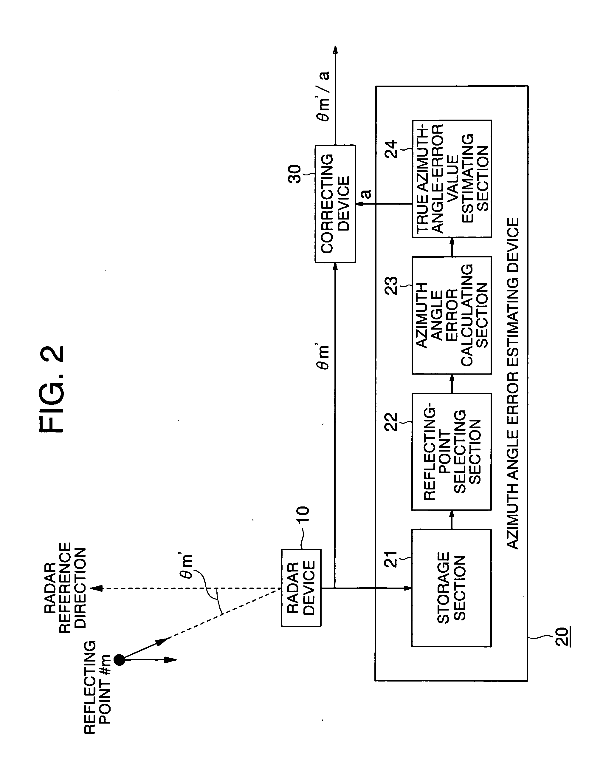
[0063] A radar system according to a second embodiment of the present invention will be described with reference to FIGS. 4 and 5. FIG. 4 is a diagram for explaining a principle of operation of a radar device of the radar system according to the second embodiment of the present invention. Note that FIG. 1 shows a case where an axis deviation angle φ=0, but FIG. 4 shows a case where an azimuth angle error “a”=1 for ease of understanding.

[0064] In FIG. 4, a radar device 10 is mounted on a movable body such as a vehicle. Reflecting points 1, 2, and 3 are radar-wave reflecting points detected by the radar device 10.

[0065] Here, the movable body mounting the radar device 10 thereon travels at an unknown speed “v” in its traveling direction. The radar device 10 has a predetermined radar reference direction. The radar reference direction is the reference direction of observed azimuth-angle values obtained by observing reflectors. It is preferred that the radar reference direction coincid...


PUM


Abstract

To obtain a radar system capable of obtaining an appropriate angular precision by calculating an angle error based on distributions of relative speeds and angles of reflecting points, and of obtaining the appropriate angular precision including an axis deviation angle by simultaneously calculating the angle error and the axis deviation angle. A radar system mounted on a movable body is provided with a radar device that calculates relative speeds and azimuth angles of plural reflecting points; an azimuth angle error estimating device that estimates an error of the azimuth angle calculated by the radar device based on the relative speeds and the azimuth angles of the plural reflecting points; and a correcting device that corrects the azimuth angle calculated by the radar device by using the azimuth angle error estimated by the azimuth angle error estimating device.

Description

BACKGROUND OF THE INVENTION [0001] 1. Field of the Invention [0002] The present invention relates to a radar system which calculates an error of an azimuth angle of a radar device that uses reflection of propagation waves such as radio waves, sound waves, or light waves, to correct the azimuth angle. [0003] 2. Description of the Related Art [0004] In recent years, development have been made on a radar device which is mounted on a movable body such as a vehicle, and has such a structure that a reflecting point of an obstacle or the like running in a traveling direction is detected to implement functions of speed control and collision prevention. In such the radar device, for the purpose of the speed control and collision prevention, it is required to obtain an azimuth angle, in addition to a distance with respect to the reflecting point and a relative speed between the own vehicle and the obstacle (or between reflecting points ?), to select an object traveling in the same traffic lan...

Claims


Application Information

Patent Timeline
IPC IPC(8): G01S7/40G01S13/931
CPCG01S7/4026G01S13/931G01S2013/9364G01S2013/9367G01S7/4972G01S7/52004G01S2007/4091G01S2007/403G01S2013/9321G01S2013/9325G01S2013/9339G01S2013/9329G01S2013/9323G01S2013/9324G01S7/403G01S7/4091
Inventor KAI, KOICHIOKAMURA, ATSUSHIHARA, ROKUZOU
Owner MITSUBISHI ELECTRIC CORP
Why Eureka
Try Eureka