Method for automatically aligning telescope

a technology of automatic alignment and telescope, applied in the field of automatic alignment of astronomical telescope, can solve the problems of easy error, difficult identification of alignment, and easy error

Active Publication Date: 2007-05-24
NANTONG SCHMIDT OPTO ELECTRICAL TECH CO LTD
View PDF2 Cites 17 Cited by
  • Summary
  • Abstract
  • Description
  • Claims
  • Application Information

AI Technical Summary

Problems solved by technology

Difficulty in Identifying Alignment Star
However, an error will occur if the coordinates for star A in the database are used, but the actual star pointed at by the GOTO telescope is star B.
Unfor

Method used


Image

  • Method for automatically aligning telescope
  • Method for automatically aligning telescope
  • Method for automatically aligning telescope

Examples


Embodiment Construction

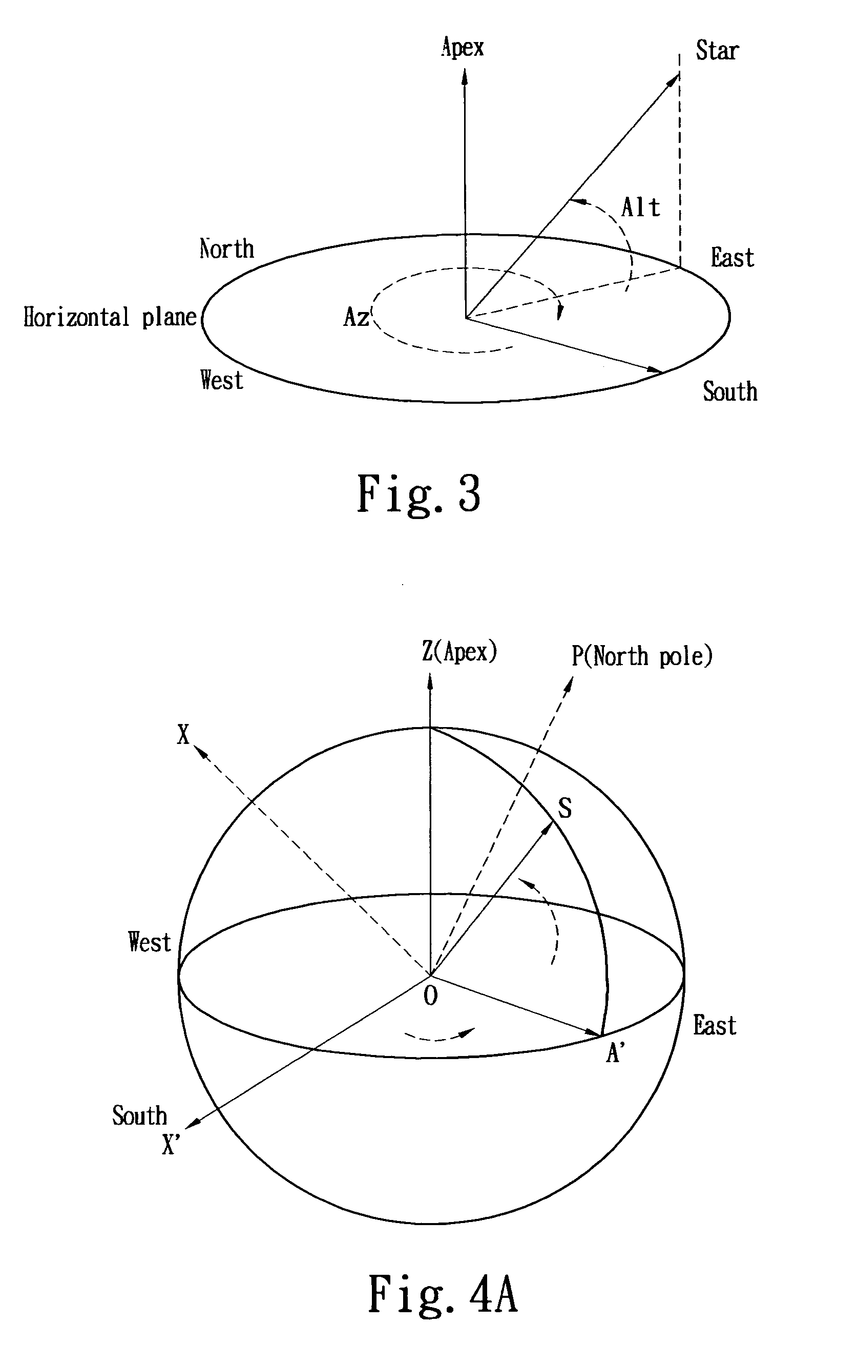
[0039] The altitude and azimuth coordinate of a star can be determined by the moving speed of the star in the altitude and azimuth coordinate. FIG. 3 shows the altitude and azimuth coordinate, wherein the position of the star can be represented by azimuth angle Az and altitude angle Alt, wherein the starting direction of the azimuth angle Az is south and the axis of rotation moving from south to west is the positive direction with an angular measurement range of −180 to +180 degrees. The starting direction of the altitude angle Alt is the horizontal plane, and the axis of rotation moving from the horizontal plane to Zenith is the positive direction with an angular measurement range of 0 to 90 degrees.

[0040] In the altitude and azimuth coordinate, the position change of the star is due to the rotation of the Earth and the speed of movement of the star can be expressed as using the following:

Az′=V0(sin Lat+tan Alt cos Az cos Lat)

Alt′=−V0 sin Az cos Lat   (1)

[0041] where Az′ is the...


PUM


Abstract

A manual controller commands a telescope mount to automatically track a specific bright star after the image of the star is located to center of an electronic eyepiece and a timer is started. The average moving speed of the bright star is calculated after a predetermined elapsed time to acquire the right ascension (RA) and the declination (DEC) coordinates of this bright star. Subsequently, the RA and DEC coordinates are compared with pre-stored data contained within a database used to identify the bright star. The celestial sphere coordinates of the telescope can be determined after a minimum of one bright star is identified. In the auto-tracking procedure, the manual controller controls movement of telescope by feedbacks of the drifting speed and direction of the specific bright star in an electronic eyepiece for the purpose of keeping the specific bright star in the center of the electronic eyepiece.

Description

BACKGROUND OF THE INVENTION [0001] 1. Field of the Invention [0002] The present invention relates to a method for automatically aligning an astronomical telescope, specifically to a method for automatically aligning a telescope with feedback control. A motor speed is controlled so as to track a bright star and the coordinates of the telescope. [0003] 2. Description of Prior Art [0004] The celestial bodies can be represented by a spherical polar coordinate on the sky. FIG. 1 shows the schematic diagram of a spherical polar coordinate with polar axis OZ, wherein the reference plane is the XOA plane vertical to the polar axis OZ and OX is a reference direction on the reference plane. The projection of OP on the reference plane is indicated by OA. Therefore, a celestial body P can be represented by the angle XOA and the angle AOP, as shown in FIG. 1. [0005] The most common sphere coordinates include celestial sphere coordinates, and altitude and azimuth coordinates, which are described ...

Claims


Application Information

Patent Timeline
IPC IPC(8): G02B23/00
CPCG02B23/16Y10S359/90
Inventor CHEN, CHIN-CHUANLIU, YAN
Owner NANTONG SCHMIDT OPTO ELECTRICAL TECH CO LTD
Why Eureka
Try Eureka