Joint arrangement for the connection of two segments of a patient bed

a joint arrangement and patient bed technology, applied in the direction of mechanical devices, manufacturing tools, couplings, etc., can solve the problems of large risk, abrupt swinging downwards of the loaded bed segment, etc., and achieve the effect of high load-bearing capacity and functional reliability

Active Publication Date: 2007-05-24
MAQUET GMBH
View PDF75 Cites 30 Cited by
  • Summary
  • Abstract
  • Description
  • Claims
  • Application Information

AI Technical Summary

Benefits of technology

[0004] The object on which the invention is based is to specify a joint arrangement of the type mentioned in the introduction which has a high load-bearing capacity and is functionally reliable.
[0006] In the joint arrangement according to the invention, the blocking faces are loaded perpendicularly to their plane, so that the load does not give rise to any spreading forces which attempt to press the joint parts away from one another. Even if, therefore, the tensioning mechanism is not tightened completely or has mistakenly been opened before the respective bed segment has been relieved of load, the blocking faces remain in engagement with one another, unchanged, so that a sudden downward swing of the loaded bed segment is avoided. Preferably, the joint parts carry, on their confronting faces one another, a toothing with a sawtooth profile, so that an adjustment of the bed segments in small steps about the axis of the shaft journal is possible.
[0007] So that the bed segments connected to one another via the joint arrangement according to the invention can also be separated from one another in a simple way, it is expedient if one of the joint parts is designed in a way known per se as a fork which can be slipped radially onto the shaft journal connected to the other joint part. In this case, to increase safety, the shaft journal carries a securing element which projects radially from it and which is dimensioned such that it closes, that is to say at least approximately fills, the fork aperture remaining after the fork has been pushed onto the shaft journal.
[0008] Closing the fork aperture prevents the situation where an operator, after slipping the fork onto the shaft journal, introduces his finger into the fork aperture and, during the pivoting of the bed segment connected to the fork, pinches his finger or fingers between a fork leg and a fixed part of the other bed segment.
[0010] For additional securing, in the joint arrangement according to the invention, on one of the joint parts, a disengageable locking element may be arranged, which, in at least one predetermined pivoting position of the two joint parts, comes into effective engagement with the other joint part in each case, in order to prevent a relative movement of the joint parts at least in the direction of movement blocked by the blocking faces. This is advantageous, for example, for setting the bed segments in situations where one of the bed segments hangs approximately vertically downwards, whilst the bed segment connected via a joint arrangement according to the invention is again directed approximately horizontally, so that a patient can kneel on the latter bed element. Since, in this case, he rests virtually with his entire weight on the horizontal bed portion, it is necessary to ensure that this bed segment does not suddenly swing downwards, specifically not even when the tensioning mechanism of the joint arrangement is inadvertently opened.

Problems solved by technology

If the tensioning mechanism is not tightened reliably or, for example, the eccentric lever is mistakenly adjusted in the opening direction, there is the risk that the loaded bed segment abruptly swings downwards.
This risk is great particularly when the patient's entire weight bears on the respective bed segment.

Method used


Image

  • Joint arrangement for the connection of two segments of a patient bed
  • Joint arrangement for the connection of two segments of a patient bed
  • Joint arrangement for the connection of two segments of a patient bed

Examples


Embodiment Construction

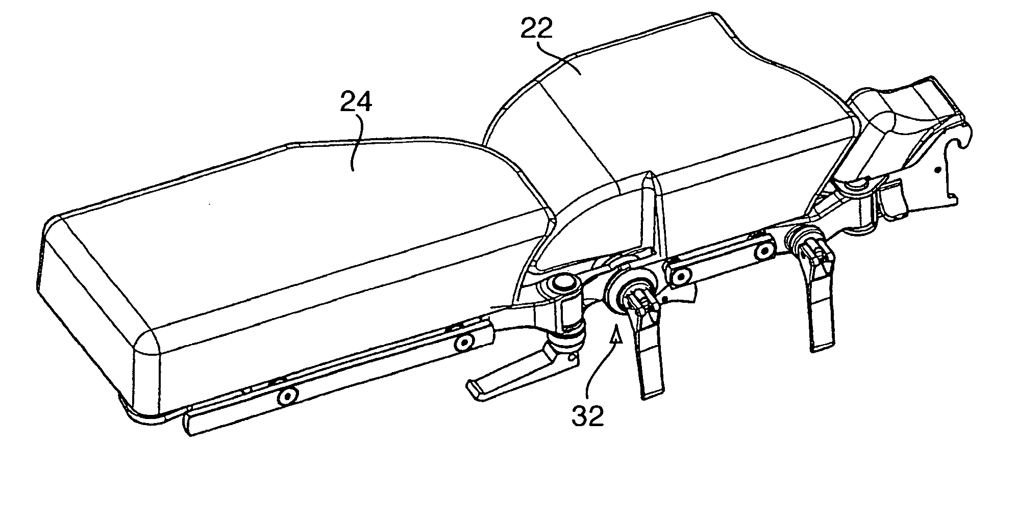
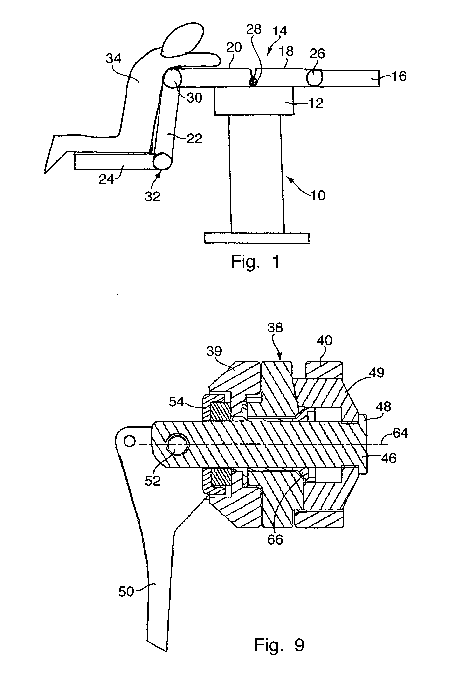
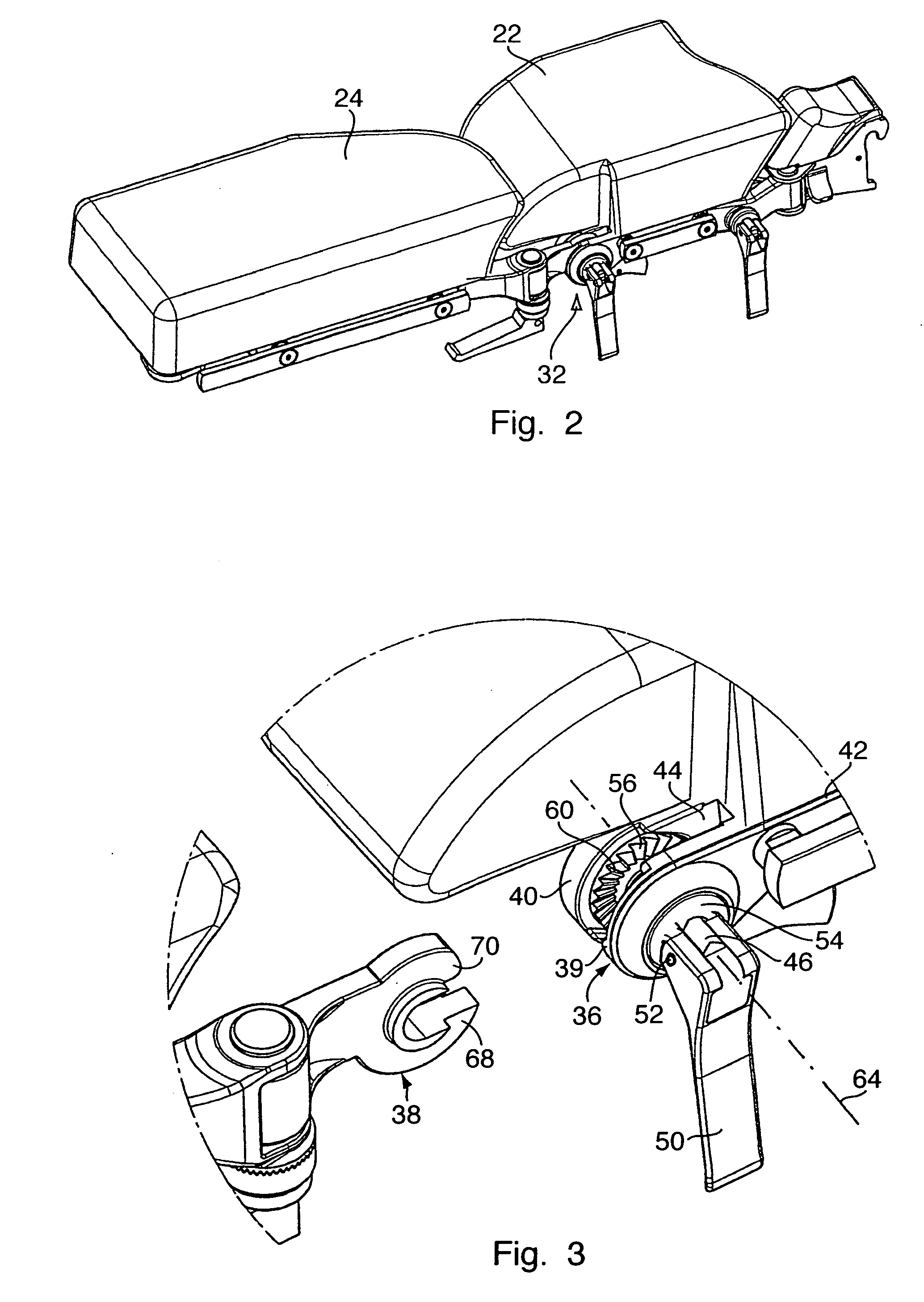
[0022]FIG. 1 shows a highly diagrammatically illustrated operating table with a table column 10, on the column head 12 of which is arranged a bed 14 which comprises a plurality of segments 16, 18, 20, 22 and 24 which are connected to one another and are adjustable in relation to one another via joints 26, 28, 30, 32. The bed portions or segments 22 and 24 are set such that the segment 22 is directed almost vertically downwards and at its lower end carries the horizontally directed segment 24. The patient 34 kneels on the latter in what is known as a rectal support. It is obvious that the patient's weight rests almost completely on the bed segment 24. Particularly in such an instance, it is necessary to ensure that the joint 32 can be fixed in this position such that the bed segment 24 does not swing away downwards completely either gradually or suddenly, even if a tensioning mechanism closing the joint arrangement is inadvertently loosened or completely opened before the bed portion...


PUM


Abstract

What is described is a joint arrangement for the articulated connection of two segments of a patient bed, with two joint parts (36, 38), each of which is connected rigidly to one of the segments and which are pivotable relative to one another about a common joint axis (64) by means of a shaft journal (46), the joint parts (36, 38) carrying, in each case on at least one of their faces confronting one another axially, blocking faces (60) intended for bearing against one another, and the joint parts (36, 38) being capable of being tensioned axially relative to one another by means of a tensioning mechanism (46, 54, 50), and the blocking faces (60) lying in each case at least approximately in a plane containing the joint axis (64).

Description

CROSS REFERENCE TO RELATED APPLICATIONS [0001] Applicant hereby claims foreign priority benefits under U.S.C. §119 from German Patent Application No. 10 2005 054 175.5 filed on Nov. 14, 2005, the contents of which are incorporated by reference herein. FIELD OF THE INVENTION [0002] The invention relates to a joint arrangement for the articulated connection of two segments of a patient bed, with two joint parts, each of which is connected rigidly to one of the segments and which are pivotable relative to one another about a common joint axis by means of a shaft journal, the joint parts carrying, in each case on at least one of their faces confronting one another axially, blocking faces intended for bearing against one another, and the joint parts being capable of being tensioned axially relative to one another by means of a tensioning mechanism. BACKGROUND OF THE INVENTION [0003] A joint arrangement of the abovementioned type is known, for example, from DE 102 53 906 A1. In the joint ...

Claims


Application Information

Patent Timeline
Patent Type & Authority Applications(United States)
IPC IPC(8): B25G3/18
CPCA61G13/08A61G13/12A61G13/122A61G13/1245A61G13/1295Y10T403/595Y10T403/32368Y10T403/32401Y10T403/32262Y10T403/59A61G2200/38A61G7/00A61G7/05
Inventor KATZENSTEIN, BERNHARD
Owner MAQUET GMBH
Why Eureka
Try Eureka