Quasi-circulator for antenna multi-coupler system

a multi-coupler and antenna technology, applied in the direction of modulation, digital transmission, duplex signal operation, etc., can solve the problems of limiting the useful range of the receiver and the distance over which full duplex radio communication can be carried out, and affecting the operation of the receiver

Inactive Publication Date: 2007-05-24
TREX ENTERPRISES CORP
View PDF3 Cites 47 Cited by
  • Summary
  • Abstract
  • Description
  • Claims
  • Application Information

AI Technical Summary

Benefits of technology

[0011] The present invention provides a multi-coupler system for isolating radio signals in a transceiver, that includes a transmitter and a receiver, to permit simultaneous transmit by the transmitter and receive by the receiver through a single antenna in the exact same or nearby frequency ranges. This is done so that in-coming receive signals, transmitted from a remotely located radio, being detected by the receiver is much stronger than the portion of the transmit signal unintentionally coupled over by the co-site (or co-located) transmitter. The invention uses a special electronic circuit, termed the quasi-circulator, to couple the antenna to both the co-located receiver and the transmitter. The invention can also be used to couple several transceivers to a single antenna. The quasi-circulator circuit includes a simulated antenna load with an impedance matched to the antenna impedance. The circuit also includes a transformer with its primary side fed asymmetrically by the antenna so that it can pass the desired receive signal with minimum attenuation. The transformer's primary is on the other hand fed symmetrically from both sides by equally small portions of the transmit power from the co-site transmitter, but these signals are 180 degrees out of phase and cancel almost completely in the transformer. The quasi-circulator works, in an unsymmetrical manner as far as the desired receive signal is concerned and in a symmetrical manner as far as the undesired co-site transmit signal is concerned, so that the receiver connected to the secondary side of the transformer receives the desired signal from the remote radio at a much higher sensitivity than it receives the leakage portion of the co-site transmit signal. Thus the invention provides a reduction in excess of 40 to 50 dB in the strength of the co-site transmitter signal at the receiver input, while leaving the signal captured by the antenna reduced by only 3 dB at the input to the receiver electronics.

Problems solved by technology

If the transmitter power is not suppressed sufficiently at the receiver input, then the sensitivity of the receiver is deteriorated, even though operation may still be possible at some impractically high receive signal levels.
Power levels at the receiver input from communication signals captured by the antenna are often in the range of −90 to −20 dBm, so insufficient suppression of the transmitter output will limit the useful range of the receiver and the distance over which full duplex radio communication may be established.
The issues of co-site interference here are prevalent and enormous.
However, magnetic circulators are not available at all frequency ranges, especially at VLF, LF, HF, VHF and UHF band, and even if available they do not cover a wide bandwidth and can not handle high power.
No prior art has been shown to adequately address co-site interference mitigation for a system in which multiple like radios are operated in a multi-octave band at very high power levels.

Method used


Image

  • Quasi-circulator for antenna multi-coupler system
  • Quasi-circulator for antenna multi-coupler system
  • Quasi-circulator for antenna multi-coupler system

Examples


Embodiment Construction

Quasi-Circulator

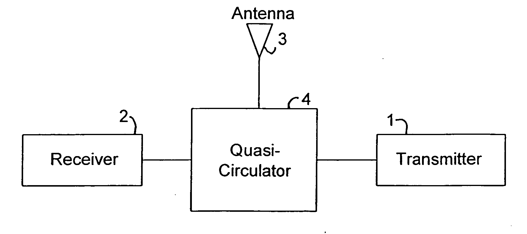
[0021] A block diagram of a preferred embodiment of the present invention which Applicant refers to as a quasi-circulator is shown in FIG. 4. A detailed diagram of the FIG. 4 embodiment is shown in FIG. 5. The principal components of the system are: transmitter 1, receiver 2, antenna 3, and quasi-circulator 4. The principal components of quasi-circulator are: matched load 5, balun transformer 6, three 3 dB splitters 8, 9a and 9b and two 10 dB amplifiers 7a and 7b. Transmit radio signals from co-site transmitter 1 are divided equally by 3 dB splitter 8 into two paths, one leading to toward antenna 3 and one leading toward matched antenna load 5. Signals received by from antenna 3 are also equally divided by 3 dB splitter 9a into two paths, one leading toward matched load 5 and the other leading toward receiver 2. The signals from antenna 3 and co-site transmitter 1 circle in the quasi-circular to reach receiver 2 using different paths and are thus affected by the qua...


PUM


Abstract

A multi-coupler system for isolating radio signals in a transceiver, that includes a transmitter and a receiver, to permit simultaneous transmit by the transmitter and receive by the receiver through a single antenna in the exact same or nearby frequency ranges. This is done so that in-coming receive signals, transmitted from a remotely located radio, being detected by the receiver is much stronger than the portion of the transmit signal unintentionally coupled over by the co-site (or co-located) transmitter. The invention uses a special electronic circuit, termed the quasi-circulator, to couple the antenna to both the co-located receiver and the transmitter. The invention can also be used to couple several transceivers to a single antenna. The quasi-circulator circuit includes a simulated antenna load with an impedance matched to the antenna impedance. The circuit also includes a transformer with its primary side fed asymmetrically by the antenna so that it can pass the desired receive signal with minimum attenuation. The transformer's primary is on the other hand fed symmetrically from both sides by equally small portions of the transmit power from the co-site transmitter, but these signals are 180 degrees out of phase and cancel almost completely in the transformer.

Description

[0001] This application claims the benefit of U.S. Provisional Applications No. 60 / 732,982, filed Nov. 23, 2005 and No. 60 / 779,791 filed on Mar. 3, 2006.[0002] This invention was made in the performance of a contract with the Office of Naval Research (Contract No. N00014-04-C-0477) and the United States Government has rights in the invention. This invention relates to radio systems and in particular radio systems having features to minimize radio interference.BACKGROUND OF THE INVENTION [0003] In many radio communications systems it is desirable to maintain continuous bi-directional data transfer (full duplex operation) between two stations. Cellular telephone systems and wireless computer networking systems are examples of two such systems. Currently, in these applications, maintaining the full duplex mode of operation requires that the telephone or radio modem transmit on one frequency range (or band) and receive on another frequency range. This technique is termed frequency diver...

Claims


Application Information

Patent Timeline
Patent Type & Authority Applications(United States)
IPC IPC(8): H04B1/44
CPCH04B1/44
Inventor DO, KY-HIEN
Owner TREX ENTERPRISES CORP
Why Eureka
Try Eureka