Dynamic spinal stabilization device and systems

a spinal column and dynamic technology, applied in the field of spinal column stabilization devices, can solve the problems of affecting the stability of the spinal column, so as to achieve the effect of limited bending or angulation

Active Publication Date: 2007-05-24
LIFE SPINE INC
View PDF28 Cites 273 Cited by
  • Summary
  • Abstract
  • Description
  • Claims
  • Application Information

AI Technical Summary

Benefits of technology

[0014] A dynamic spine stabilization element of a spine stabilization system or assembly, includes first and second spinal rods or rod segments that are coupled to one another via a coupling device. The coupling device provides movement or motion of one or more of the spinal rod segments with respect to the coupling device and / or with respect to the other spinal rod segment. The present invention thus provides spinal stabilization elements for spinal stabilization systems that allow for limited angulation (e.g. bending) between spinal rod segments of the spinal stabilization element. This allows for limited movement of the vertebra connected by the present dynamic stabilization element.
[0016] In another form, the first and second spinal rod segments are connected via a bendable or flexible coupling device. The coupling device is adapted to allow limited flexing, bending or angulation as between the associated spinal rod segments during use. Particularly, the coupling device allows for 360° angulation.
[0017] Ends of the spinal rod segments may be configured to prevent or limit rotation of the spinal rod segments. The configured ends may cooperate with the coupling device to achieve the limitation on rotational movement. In another form, the coupling device and / or the configured ends of the spinal rod segments, allow for limited axial movement between rod segments.

Problems solved by technology

In the case of degenerative disc disease, spinal trauma and the like, such conditions are often painful and / or physically deforming.
A drawback of rigid fixation relates to the loading that occurs on the stabilizing assemblies and especially on the anchoring sites during normal activity.
These loads may result in loosening of the assembly from the vertebrae or even breaking of the assembly.
Moreover, spinal fusion limits the range of a patient's motion.
These semi-rigid spine fixation systems, however, are far from effective and / or efficient.

Method used


Image

  • Dynamic spinal stabilization device and systems
  • Dynamic spinal stabilization device and systems
  • Dynamic spinal stabilization device and systems

Examples


Embodiment Construction

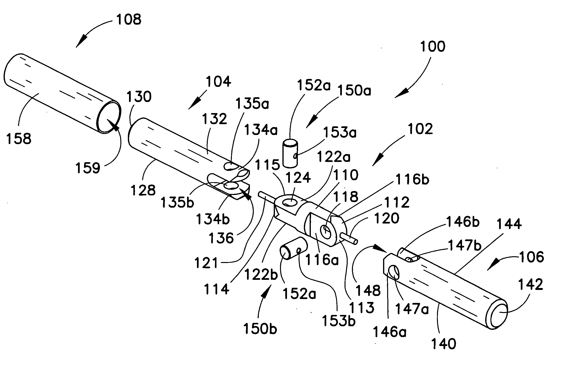
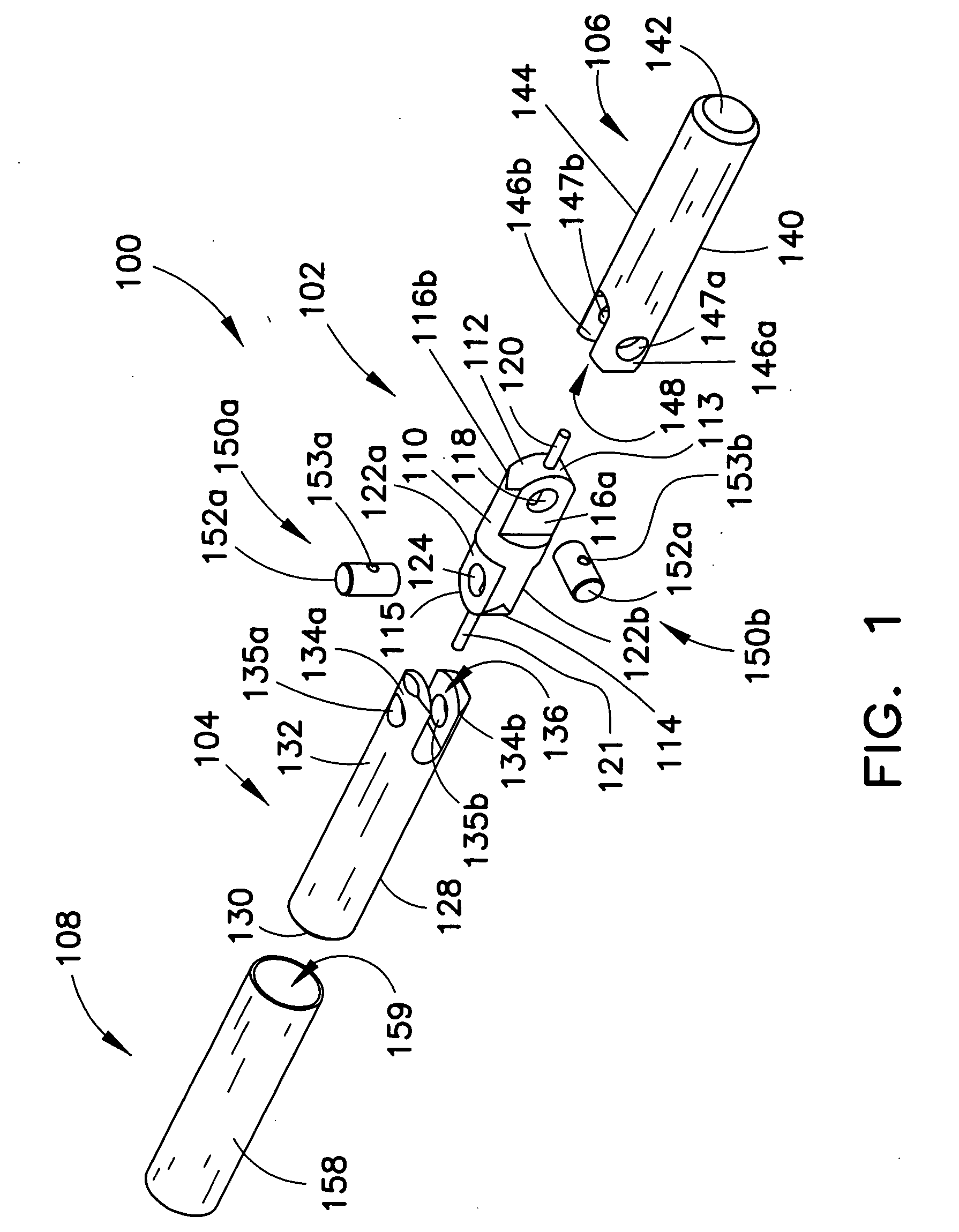
[0046]FIG. 1 depicts an exploded view of an embodiment of a dynamic spinal stabilization element or construct generally designated 100 especially for use in a spinal stabilization system or assembly. The dynamic spinal stabilization element 100 is a rod assembly that is designed to be retained at both ends to bone anchoring elements such as bone screws (see e.g. FIGS. 23-26) of the spinal stabilization assembly. The dynamic spinal stabilization element 100 allows motion or movement relative to first and second rods or rod segments 104 and 106. Particularly, the dynamic spinal stabilization element 100 allows motion or movement of the rod segments 104, 106 in two planes of motion, the two planes of motion being perpendicular to one another. The dynamic spinal stabilization element 100 provides a jointed spinal rod.

[0047] The dynamic spinal stabilization element 100 has a coupling element 102 that provides jointed coupling or attachment to the rod segments 104, 106. The coupling elem...


PUM


Abstract

A dynamic spine stabilization element of a spine stabilization assembly includes first and second spinal rod segments that are coupled to one another via a connector. The connector allows movement of a spinal rod segment with respect to the coupling device and / or with respect to another spinal rod segment. This provides limited angulation (e.g. bending) between spinal rod segments allowing for limited movement of the vertebra connected by the present dynamic stabilization element. The connector may allow pivoting motion of the rod segments relative to the coupling device and relative to the other rod segment such as pivoting motion of one rod segment in a first plane and pivoting motion of the other rod segment in a second plane that is perpendicular to the first plane. The connector may also be bendable or flexible. In this form, the connector allows limited flexing, bending or angulation as between the associated spinal rod segments during use. Moreover, ends of the spinal rod segments may be configured to prevent or limit rotation of the spinal rod segments. The configured ends may cooperate with the coupling device to achieve the limitation on rotational movement.

Description

RELATED APPLICATIONS [0001] This patent application claims the benefit of and / or priority to U.S. Provisional Patent Application No. 60 / 738,380 filed Nov. 18, 2005, entitled “Dynamic Spinal Stabilization Devices and Systems” the entire contents of which is specifically incorporated herein by reference.BACKGROUND [0002] 1. Field of the Invention [0003] The present invention provides devices for the stabilization of the spinal column and, more particularly, to dynamic devices for the stabilization of the spinal column. [0004] 2. Background Information [0005] A significant portion of the population suffers from spinal problems. Such spinal problems may be attributable to disease, trauma and / or other event. In the case of degenerative disc disease, spinal trauma and the like, such conditions are often painful and / or physically deforming. Depending on the situation, the pain and complications caused by these conditions may require that one or more vertebra, facet joints, and / or intervert...

Claims


Application Information

Patent Timeline
Patent Type & Authority Applications(United States)
IPC IPC(8): A61F2/30
CPCA61B17/7004A61B17/7023A61B17/7031A61B17/7032A61B17/705
Inventor BUTLER, MICHAEL S.MILELLA, MICHAEL J. JR.
Owner LIFE SPINE INC
Why Eureka
Try Eureka