Upnp av device interworking method of upnp-based network system
- Summary
- Abstract
- Description
- Claims
- Application Information
AI Technical Summary
Benefits of technology
Problems solved by technology
Method used
Image

Examples
first embodiment
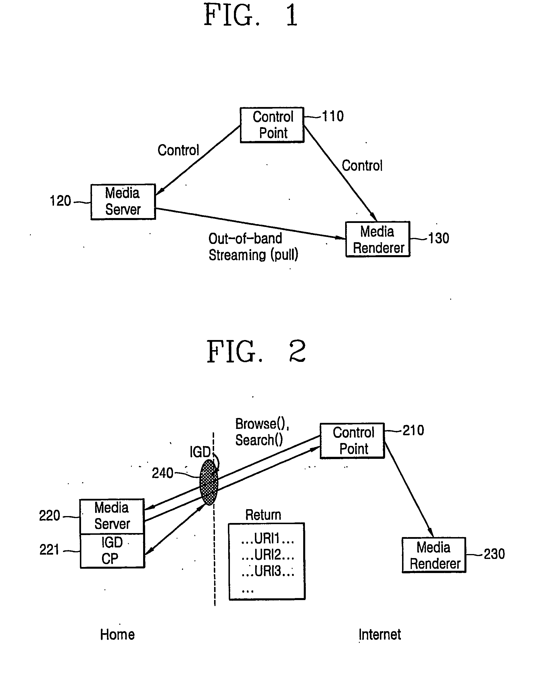
[0026]FIG. 2 is a structure diagram illustrating a UPnP AV device control system in which a CP and an MR are located on a common internet, an MS is located on a home network, and an IGD for connecting the CP and the MS is included in accordance with the present invention.
[0027] As illustrated in FIG. 2, the MS 220 includes a UPnP IGD CP 221, and the IGD 240 connects the CP 210 located on the common internet and the MS 220 located on the home network. Here, the IGD 240 is an independent gateway device or a personal computer (PC) serving as a gateway.
[0028] The operation of the UPnP AV device control system in accordance with the first embodiment of the present invention will now be described.
[0029] The CP 210 located on the common internet is connected to the MS 220 through the IGD 240 by confirming a description address including a list on devices and services. In order to obtain an address of predetermined contents from the MS 220, the CP 210 transmits Browse( ) or Search( ) acti...
second embodiment
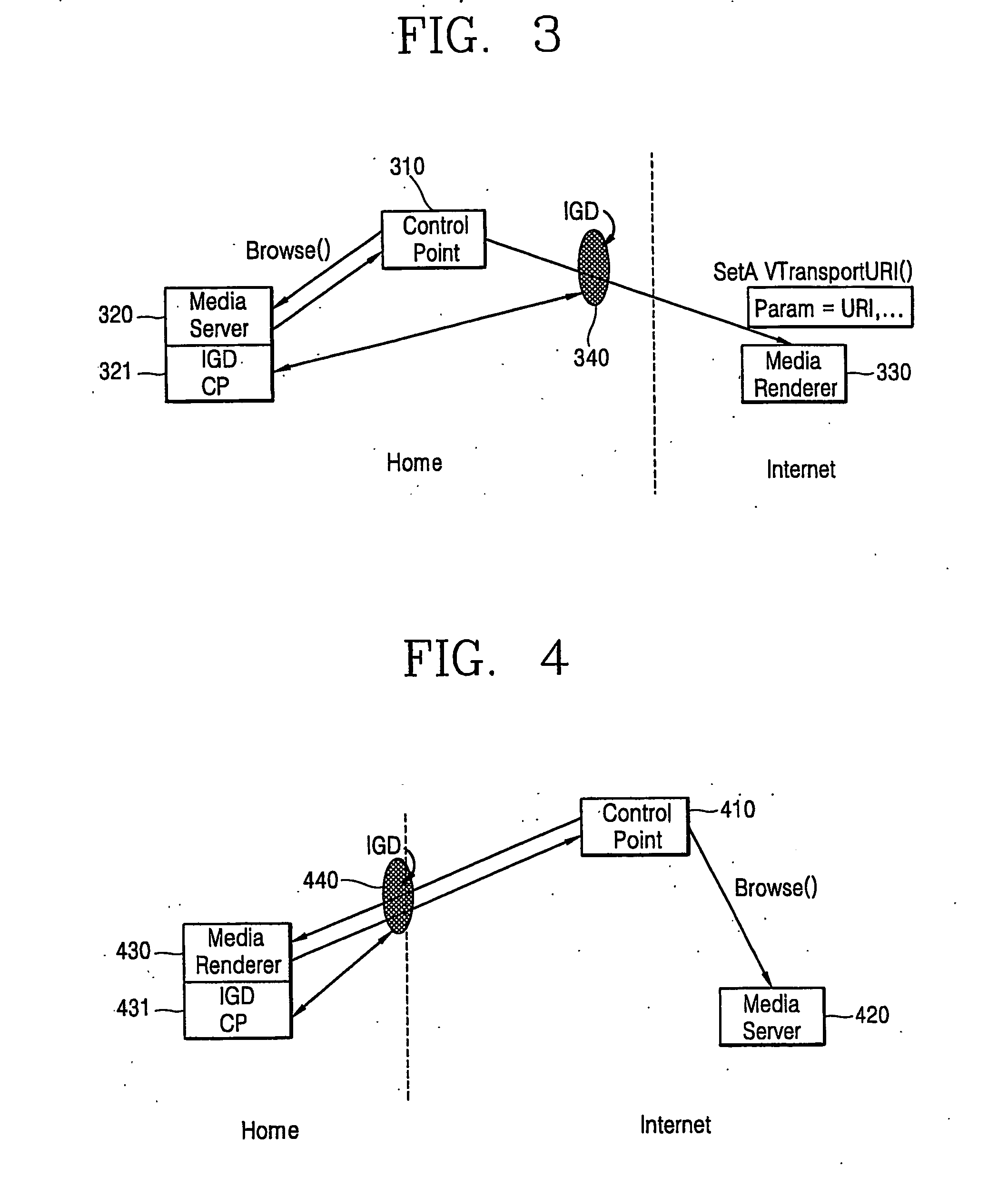
[0034]FIG. 3 is a structure diagram illustrating a UPnP AV device control system in which a CP and an MS are located on a home network and an MR is located on a common internet in accordance with the present invention.
[0035] As shown in FIG. 3, the MS 320 includes a UPnP IGD CP 321, and an IGD 340 connects the CP 310 located on the home network and the MR 330 located on the common internet. Here, the IGD 340 is an independent gateway device or a PC serving as a gateway.
[0036] The operation of the UPnP AV device control system in accordance with the second embodiment of the present invention will now be described.
[0037] The CP 310 located on the home network confirms a description address including a list on devices and services, and transmits Browse( ) action to the MS 320 located on the home network to obtain an address of predetermined contents. The MS 320 transmits an action return value including a URI to the CP 310. The CP 310 selects the MR 330 located on the common internet...
third embodiment
[0041]FIG. 4 is a structure diagram illustrating a UPnP AV device control system in which a CP and an MS are located on a common internet and an MR is located on a home network in accordance with the present invention.
[0042] As depicted in FIG. 4, the MS 430 includes a UPnP IGD CP 431, and an IGD 440 connects the CP 410 located on the common internet and the MR 430 located on the home network. Here, the IGD 440 is an independent gateway device or a PC serving as a gateway.
[0043] The operation of the UPnP AV device control system in accordance with the third embodiment of the present invention will now be described.
[0044] The CP 410 located on the common internet confirms a description address including a list on devices and services, and selects the MR 430 located on the home network through the IGD 440 as a device for playing back contents. When the CP 410 located on the common internet and the MR 430 located on the home network are connected to each other, the NAT is set up to t...
PUM
 Abstract
Description
Claims
Application Information
 - R&D Engineer
- R&D Manager
- IP Professional
- Industry Leading Data Capabilities
- Powerful AI technology
- Patent DNA Extraction
Browse by: Latest US Patents, China's latest patents, Technical Efficacy Thesaurus, Application Domain, Technology Topic.
© 2024 PatSnap. All rights reserved.Legal|Privacy policy|Modern Slavery Act Transparency Statement|Sitemap