
Decanting bottle and method

Inactive Publication Date: 2007-05-31
GRACE CHARLOTTE
View PDF11 Cites 42 Cited by
  • Summary
  • Abstract
  • Description
  • Claims
  • Application Information

AI Technical Summary

Benefits of technology

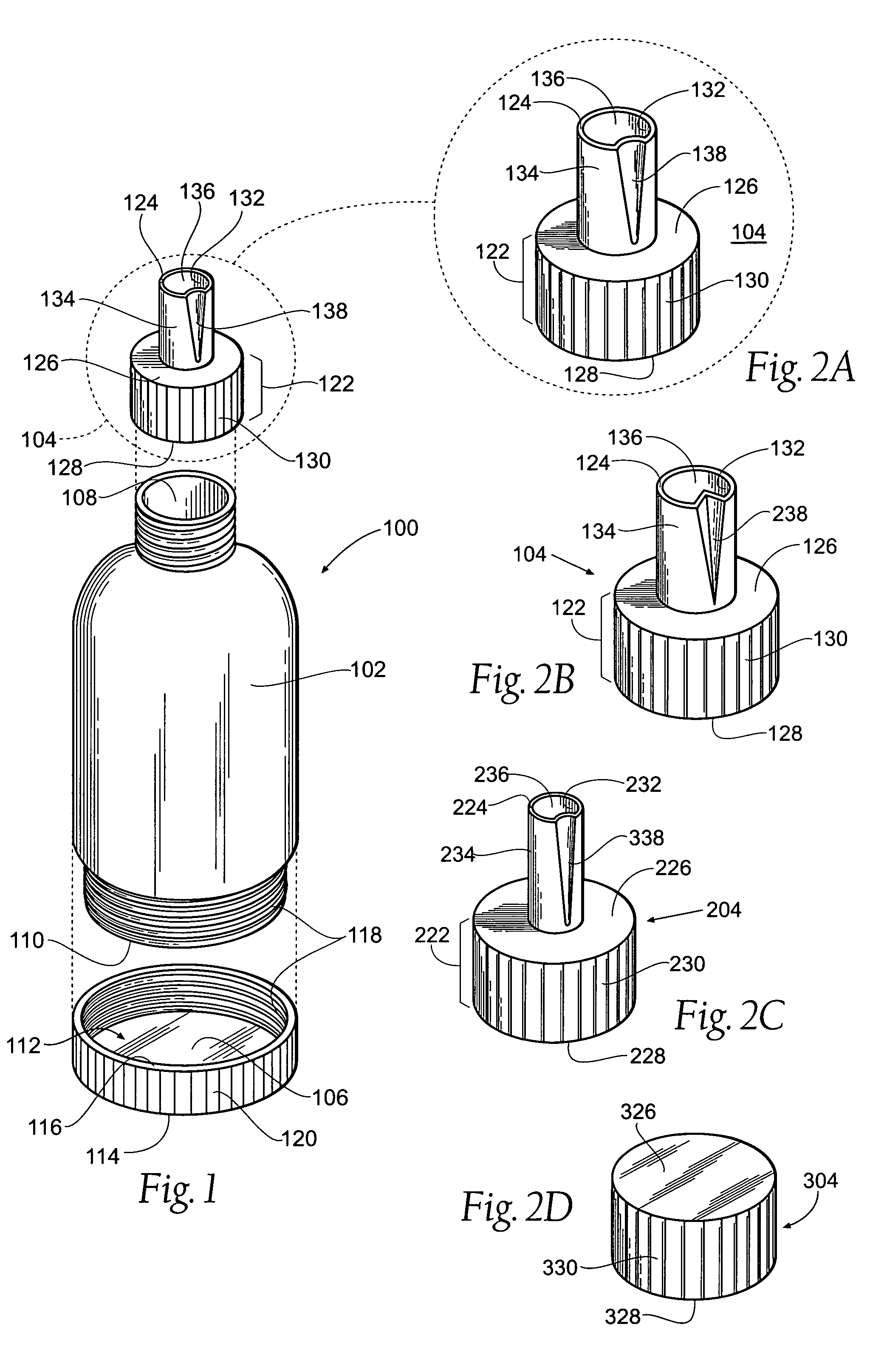
[0007] According to the present invention there is provided a device for containing and decanting fluid comprising a semi-rigid fluid reservoir having an opening. A cap is adapted to be removably coupled to the reservoir at the opening, and, if warranted, a bottom lid may be adapted to be removably coupled to the reservoir at an opening located at the opposite end of the first-mentioned opening. The cap has a longitudinally extending, tubular nozzle that has at least one airway formed into its outer wall. The airway allows air to escape from a container that is being filled with the fluid contained in the fluid reservoir, thus preventing spillage.
[0009] Also, since the airway is formed on the exterior surface of the nozzle, cleaning the nozzle and airway will be simplified.

Problems solved by technology

This decanting process is difficult and may result in spillage and ultimate loss of product.
Refill liquid is sometimes purchased in pouches or other collapsible containers that make the refilling process cumbersome and difficult.
This is especially true in the case of a viscous fluid such as shampoo, or a more viscous fluid such as petroleum jelly, wherein the fluid stream poured from a pouch or jar may be wider than the mouth of the bottle to be refilled, thus resulting in spillage.
However, depending upon the style of bottle being filled, the nozzle may not be the correct size to allow insertion into the bottle, or the nozzle may occupy the entire surface area of the bottle opening, thereby trapping air in the bottle and preventing fluid flow.
A further problem is that refill pouches may be flimsy and difficult to manage with a single hand.
Yet another problem is that nozzles may be difficult to clean and thus may not be reused.
Although some nozzles have been developed to allow air to escape a filling bottle, the air passageways are internal to the nozzle walls, thus preventing easy access for cleaning if fluid becomes lodged in the air channels.

Method used


Image

  • Decanting bottle and method
  • Decanting bottle and method
  • Decanting bottle and method

Examples


Embodiment Construction

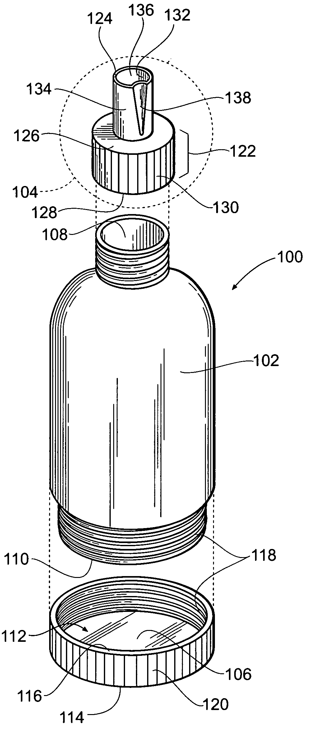
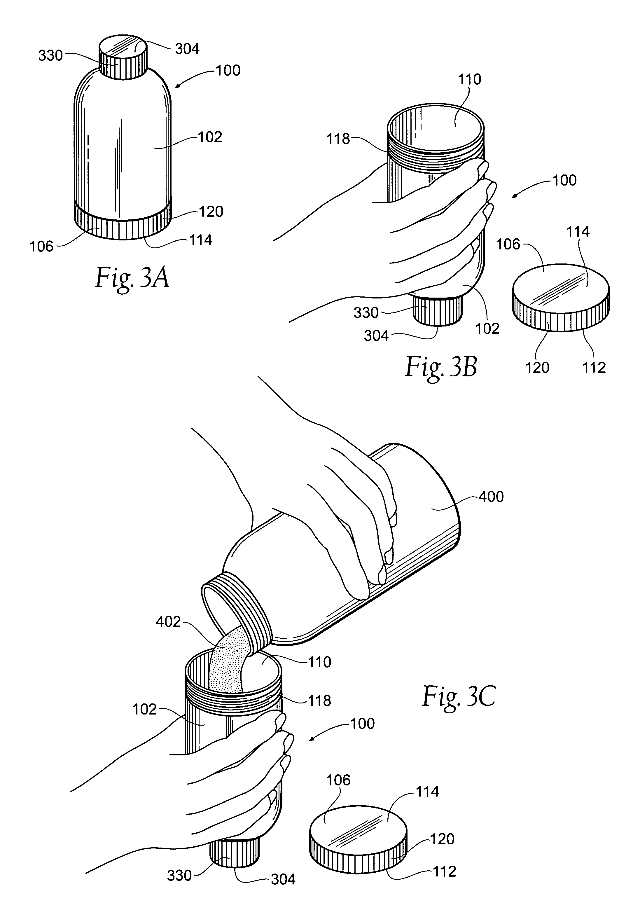
[0019]FIG. 1 shows an exploded view of an embodiment of the decanting device 100 according to the present invention. A preferred embodiment of the decanting device 100 preferably comprises a fluid reservoir 102, a cap 104, and a bottom lid 106. The fluid reservoir 102 has a top aperture 108 and a bottom aperture 110, although the present invention may be practical without the bottom aperture 110. The words ‘top’ and ‘bottom,’ as used herein, refer generally to different locations and no specific physical orientation is implied. Preferably, the reservoir 102 has a conventional cylindrical bottle shape, wherein the top aperture 108 is smaller than the bottom aperture 110. The reservoir 102 is preferably sized to comfortably fit in an average sized adult human hand. The reservoir 102 is preferably manufactured from a semi-rigid material, such as a semi-rigid plastic, so as to provide stability, as well as the ability to be squeezed by the human hand to thereby force a fluid out of the ...


PUM

PropertyMeasurementUnit
Viscosityaaaaaaaaaa

Abstract

A decanting device is provided with a cap having a longitudinally extending, tubular nozzle with an airway debossed lengthwise on the outer surface of the nozzle. The decanting device may also have a bottom lid and a fluid reservoir with a top aperture and a bottom aperture. The cap is adapted to be removably coupled to the device at the top aperture and a bottom lid is adapted to be removably coupled to the device at the bottom aperture. Such device is useful in decanting liquids of varying viscosity since the nozzle airway allows air to escape a container that is being filled with a liquid from the decanting device.

Description

BACKGROUND OF THE INVENTION [0001] The present invention relates generally to tubes and bottles and more specifically to a device for filling tubes and bottles with a fluid while at the same time allowing air to escape. [0002] Fluids, such as perfume, after-shave, lotion, shampoo, and the like, are often sold in containers that are rather large and intended for stationary use. However, it may be desirable to travel with such fluids by first decanting the fluid into a smaller travel container. This decanting process is difficult and may result in spillage and ultimate loss of product. [0003] Further, a product purchased for use in the home may, itself, be intended for refill. Refill liquid is sometimes purchased in pouches or other collapsible containers that make the refilling process cumbersome and difficult. This is especially true in the case of a viscous fluid such as shampoo, or a more viscous fluid such as petroleum jelly, wherein the fluid stream poured from a pouch or jar ma...

Claims


Application Information

Patent Timeline
IPC IPC(8): B65B3/04
CPCB65D1/06B65D47/06
Inventor GRACE, CHARLOTTE
Owner GRACE CHARLOTTE
Learn More