Heat sink for distributing a thermal load

a technology of heat sinks and heat sinks, which is applied in the direction of lighting and heating apparatus, semiconductor/solid-state device details, and laminated elements, etc., can solve the problems of generating a considerable amount of heat, consuming significant amounts of power, and requiring a significant amount of power to operate these computer processors

Inactive Publication Date: 2007-05-31
IBM CORP
View PDF18 Cites 14 Cited by
  • Summary
  • Abstract
  • Description
  • Claims
  • Application Information

AI Technical Summary

Problems solved by technology

Operating these computer processors requires a significant amount of power, and often such processors can consume over 100 watts.
Consuming significant amounts of power generates a considerable amount of heat.
Unless the heat is removed, heat generated by a computer processor may degrade or destroy the processor's functionality.
Current heat sinks, however, only provide one or two cooling surfaces with attached fins for dissipating the heat absorbed by the heat sinks.
Such heat sinks are often unable to remove the heat necessary to prevent damage to today's computer processors because physical limitations may prevent a system designer from designing cooling surface large enough or fins tall enough to dissipate the required amount of heat from the processor.
Combining a fan with a heat sink may improve the ability to remove heat from the computer processor, but such a combination also may not be sufficient to prevent damage in today's computer processors.
Heat pipes are capable of removing large quantities of heat from a computer processor, but heat pipes may not be an option where a system designer requires a local cooling solution.
Refrigeration systems also effectively remove heat, but such systems are typically large and expensive.

Method used


Image

  • Heat sink for distributing a thermal load
  • Heat sink for distributing a thermal load
  • Heat sink for distributing a thermal load

Examples


Embodiment Construction

Detailed Description

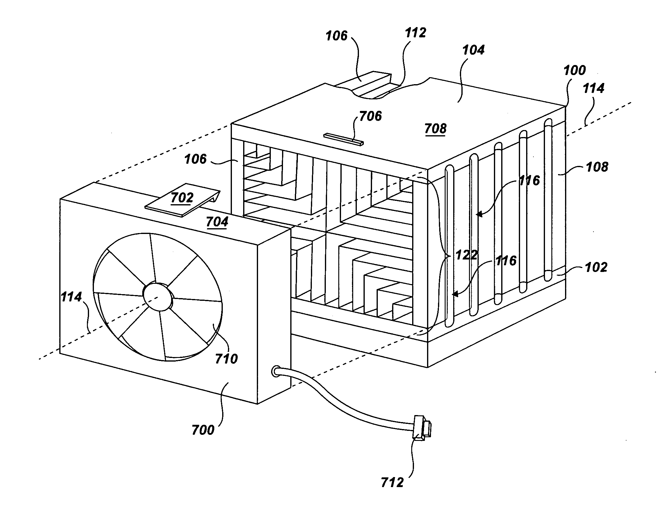
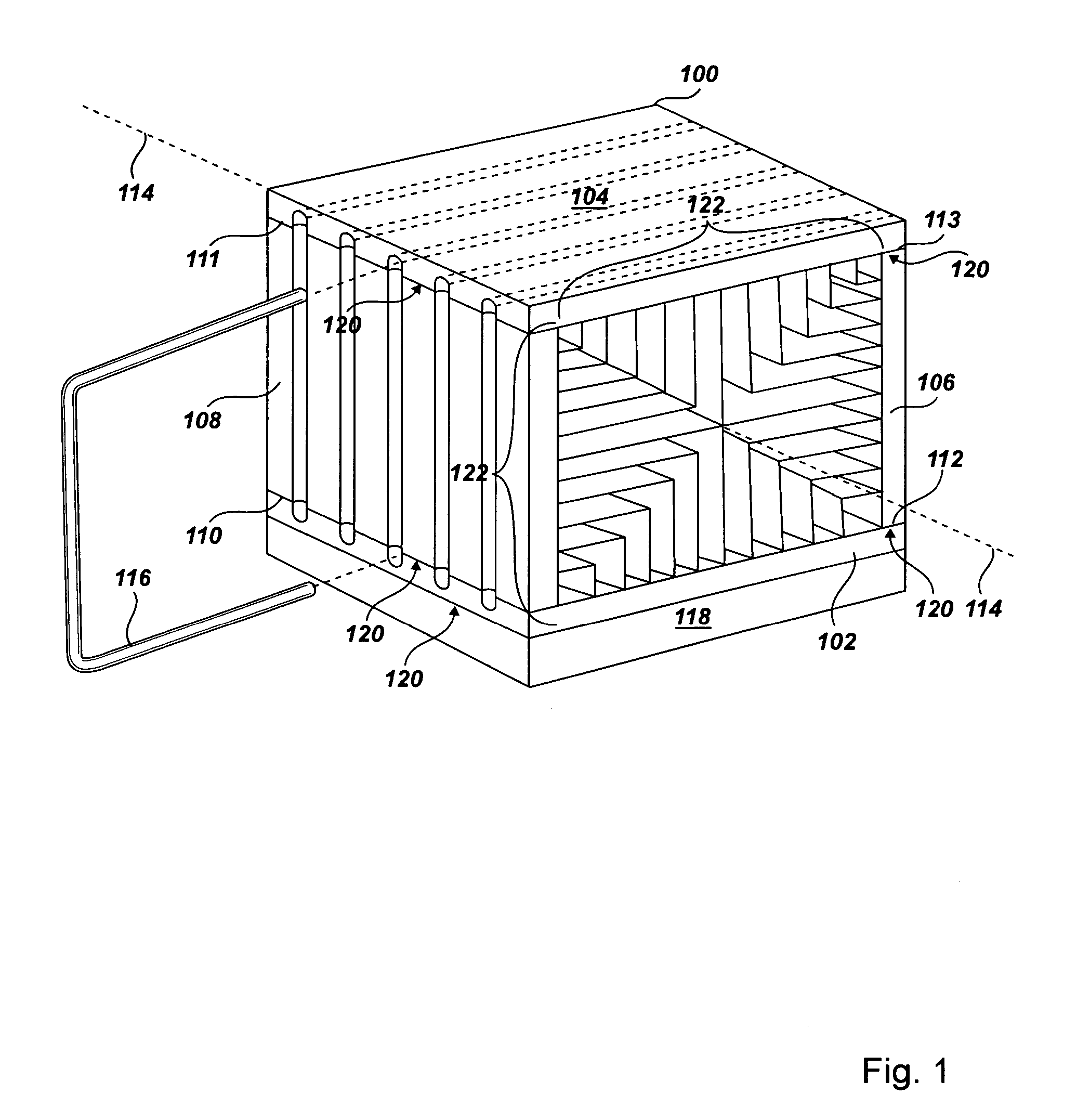
[0016] Exemplary heat sinks for distributing a thermal load according to embodiments of the present invention are described with reference to the accompanying drawings, beginning with FIG. 1. FIG. 1 sets forth a perspective view of an exemplary heat sink (100) for distributing a thermal load according to embodiments of the present invention. The thermal load is the rate of thermal energy produced over time from the operation of an integrated circuit package (118) such as, for example, a computer processor or memory chip and is typically expressed in units of Watts.

[0017] In the example of FIG. 1, the heat sink (100) is a thermal conductor configured to absorb and dissipate the thermal load from the integrated circuit package (118) thermally connected with the heat sink (100). Thermal conductors used in designing the heat sink (100) may include, for example, aluminum, copper, silver, aluminum silicon carbide, or carbon-based composites. Heat sink (100) absorbs t...


PUM


Abstract

A heat sink for distributing a thermal load is disclosed that includes a bottom plate, a top plate, a right plate, and a left plate, the plates connected along edges so as to define a space generally cubical in shape with four closed sides and two open ends; heat-dissipating fins connected to each plate, the fins spaced apart in parallel and extending from each plate towards a central axis of the heat sink; and a thermal transport connected to the plate receiving the thermal load and to at least one of the other plates so as to distribute the thermal load among the plates of the heat sink.

Description

BACKGROUND OF THE INVENTION [0001] 1. Field of the Invention [0002] The field of the invention is heat sinks for distributing a thermal load. [0003] 2. Description of Related Art [0004] The development of the EDVAC computer system of 1948 is often cited as the beginning of the computer era. Since that time, users have relied on computer systems to simplify the process of information management. Today's computer systems are much more sophisticated than early systems such as the EDVAC. Such modern computer systems deliver powerful computing resources to provide a wide range of information management capabilities through the use of computer software such as database management systems, word processors, spreadsheets, client / server applications, web services, and so on. [0005] In order to deliver powerful computing resources, computer system designers must design powerful computer processors. Current computer processors, for example, are capable of executing billions of computer program ...

Claims


Application Information

Patent Timeline
Patent Type & Authority Applications(United States)
IPC IPC(8): H05K7/20
CPCF28D15/0233F28D15/0266F28F3/02H01L23/373H01L23/427H01L2924/0002H01L23/467H01L2924/00
Inventor FOSTER, JIMMY G. SR.HARDEE, DONNA C.KEENER, DON S.WOLFORD, ROBERT R.
Owner IBM CORP
Why Eureka
Try Eureka