Pneumatic pusher

a pneumatic pusher and push rod technology, applied in the field of pneumatic pushers, can solve the problems of increasing the failure rate, reducing the discharge speed, so as to improve the discharge speed, reduce the failure rate, and smooth the pneumatic push action

Active Publication Date: 2007-05-31
SHENG CHIH SHENG
View PDF7 Cites 20 Cited by
  • Summary
  • Abstract
  • Description
  • Claims
  • Application Information

AI Technical Summary

Benefits of technology

[0010] A primary object of the invention to provide a pneumatic pusher that eliminates the drawbacks of the return spring in the above-mentioned disclosure and ensures a reliable reciprocating displacement of the delivery tube, thereby resulting in a smooth pneumatic pushing action, a decrease of the failure rate, and an improvement of the discharge speed.
[0011] Another object of the present invention to provide a pneumatic pusher that is provided with a rubber ring at the front end of the delivery tube for reducing the impact force acting on the object to be discharged.
[0012] A further object of the present invention to provide a pneumatic pusher that is provided with a bolt for adjusting the reciprocating action of the moving body, thereby ensuring a convenient control over the change of the flow field pressure.

Problems solved by technology

However, it contains a great number of mechanic components, thereby resulting in the rise of the failure rate.
Meanwhile, the discharge speed will be considerably restricted.
After prolonged service, the return spring will create fatigue in elasticity, thereby resulting in decrease of the discharge speed.
Thus, the reciprocating process of the delivery tube becomes problematic due to mismatch in speed.
Meanwhile, the front end of the delivery tube lacks an elastic rubber ring such that the front end of the delivery tube made of metal will be in direct contact with the paint ball and therefore causes an easy burst of the paint ball.
In addition, it is not possible for the aforementioned disclosure to adjust the reciprocating process of a flow-guiding piston within a flow-guiding body and therefore to change the flow field pressure.

Method used


Image

  • Pneumatic pusher
  • Pneumatic pusher
  • Pneumatic pusher

Examples


Embodiment Construction

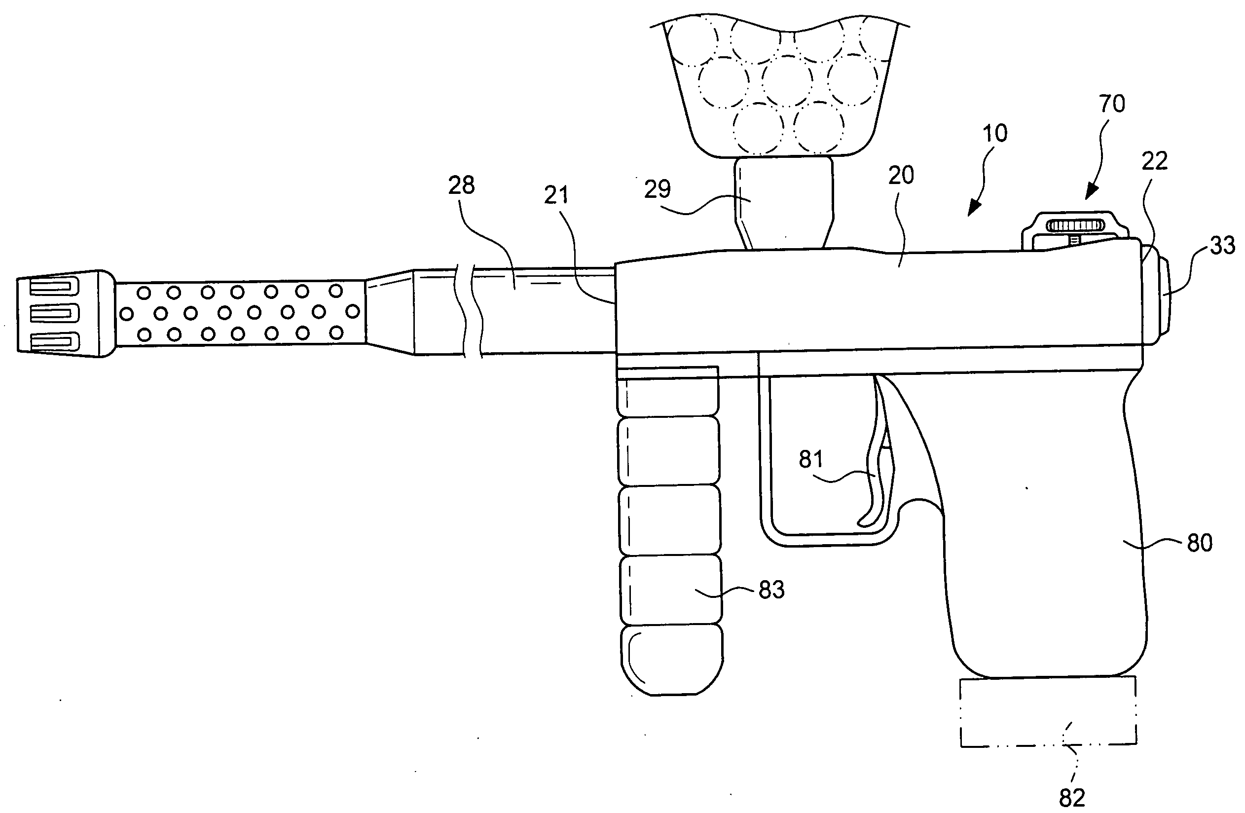
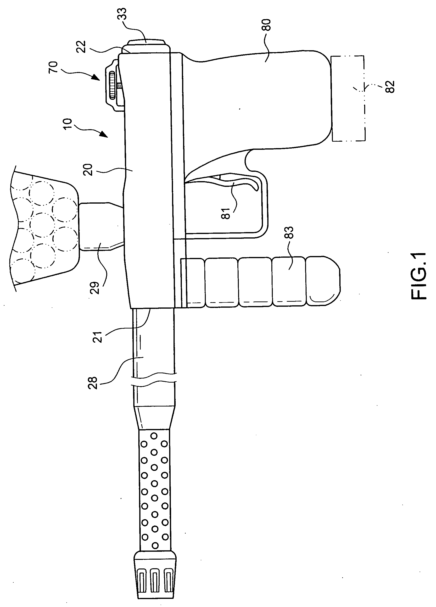
[0022] Referring to FIG. 1, a pneumatic pusher 10 in accordance with the present invention is applied to a paintball gun. However, the application should not be limited thereto. In other words, the pneumatic pusher 10 can be employed for BB guns, nailing guns, etc. The paintball gun is taken as example in the following description.

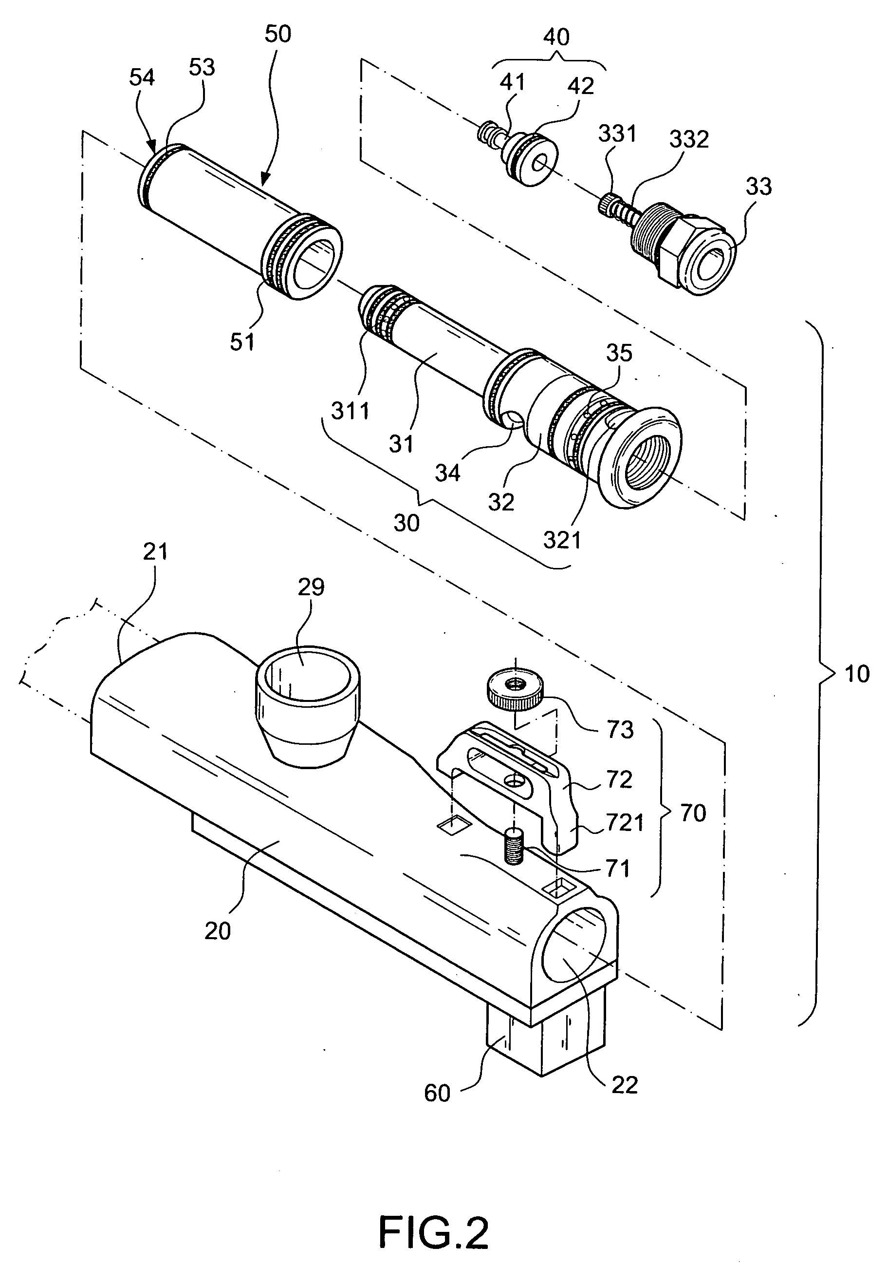
[0023] As shown in FIGS. 2 and 3, the pneumatic pusher 10 in accordance with the invention includes a main body 20, a flow-guiding body 30, a moving body 40, and a delivery tube 50.

[0024] The main body 20 includes a hollow tube configuration with a first orifice 21 and a second orifice 22 at both ends thereof. The side of the main body 20 includes a first air inlet 23 for injecting an external pressurized gas A and a first air outlet 24 for guiding the air flow. The first air outlet 24 externally communicates with a gas-distributing chamber 25. The gas-distributing chamber 25 is controlled by a moving plunger 61 in an open or a close state. The side of t...


PUM


Abstract

A pneumatic pusher having a main body, a flow-guiding body, a moving body, and a delivery tube. The flow-guiding body includes a front tube with a smaller diameter and a rear tube with a larger diameter. The delivery tube is mounted on the front tube in such a way that the outer wall of the delivery tube and the inner wall of the main body define a return pressure chamber. A first gas-distributing channel extending from a first air outlet at one side of the main body leads directly to the inner side of the delivery tube. The side of the first air inlet of the main body communicates with a second gas-distributing channel. The second gas-distributing channel includes an exit located at one side of the return pressure chamber of the delivery tube. The air pressure provided through the second gas-distributing channel serves as cushioning force in pushing the delivery tube outwardly. When the moving plunger blocks the gas distributing chamber in such a way that the gas is stopped to be injected through the first gas distributing channel into the pushing chamber for bringing the delivery tube forward, the gas pressure injected through the second gas distributing channel into the return pressure chamber acts as inward return force for the delivery tube. Therefore, the reciprocating movement of the delivery tube on the front tube can be completely done by the airflow.

Description

BACKGROUND OF THE INVENTION [0001] 1 . Field of the Invention [0002] The invention relates to a pneumatic pusher, and more particularly to a pneumatic pusher that allows a change of the flow field pressure by controlling an airflow channel in an open and a close state. Accordingly, an object to be discharged can be pushed forward in a pneumatic manner. The pneumatic pusher is primarily applied to the paintball guns. However, it should not be limited thereto. [0003] 2. Description of the Related Art [0004] Most of the paintball guns employ a mechanic pusher to control the discharge of the paintball. However, it contains a great number of mechanic components, thereby resulting in the rise of the failure rate. Meanwhile, the discharge speed will be considerably restricted. [0005] The inventor of the present invention has disclosed a “PAINTGUN WITH PENUMATIC FEEDING AND DISCHARGING PROCESS” in U.S. Pat. No. 6,601,780 and pub.No:US2005 / 005924A1 in which the paintballs are discharged in a...

Claims


Application Information

Patent Timeline
Patent Type & Authority Applications(United States)
IPC IPC(8): B05B9/00B05B9/01B05B9/08
CPCF41B11/721
Inventor SHENG, CHIH-SHENG
Owner SHENG CHIH SHENG
Why Eureka
Try Eureka