
Starter system for portable internal combustion engine electric generators using a portable universal battery pack

a technology of internal combustion engine and starter system, which is applied in the direction of engine starters, machines/engines, mechanical equipment, etc., can solve the problems of motor and fixed battery adding size, bulk and weight to the portable generator

Inactive Publication Date: 2007-05-31
BLACK & DECKER INC
View PDF62 Cites 43 Cited by
  • Summary
  • Abstract
  • Description
  • Claims
  • Application Information

AI Technical Summary

Benefits of technology

[0007] In accordance with an aspect of the invention, a portable power driven system has a manually movable frame. An internal combustion engine and a generator device that generates AC power may be supported on the frame. The internal combustion engine drives the generator device. An electrically powered starting device is coupled to the internal combustion engine. A control panel is coupled to the frame and includes at least one AC outlet and a battery receptacle that is electrically coupled to the starting device. The battery receptacle is materially the same as a foot of a cordless power tool that receives a battery pack. The battery pack for the cordless power tool may be permanently mounted in the battery receptacle and provides electrical power to the starting device.

Problems solved by technology

The starter motor and fixed battery add size, bulk and weight to the portable generator.

Method used


Image

  • Starter system for portable internal combustion engine electric generators using a portable universal battery pack
  • Starter system for portable internal combustion engine electric generators using a portable universal battery pack
  • Starter system for portable internal combustion engine electric generators using a portable universal battery pack

Examples


Embodiment Construction

[0038] The following description of the preferred embodiment(s) is merely exemplary in nature and is in no way intended to limit the invention, its application or uses.

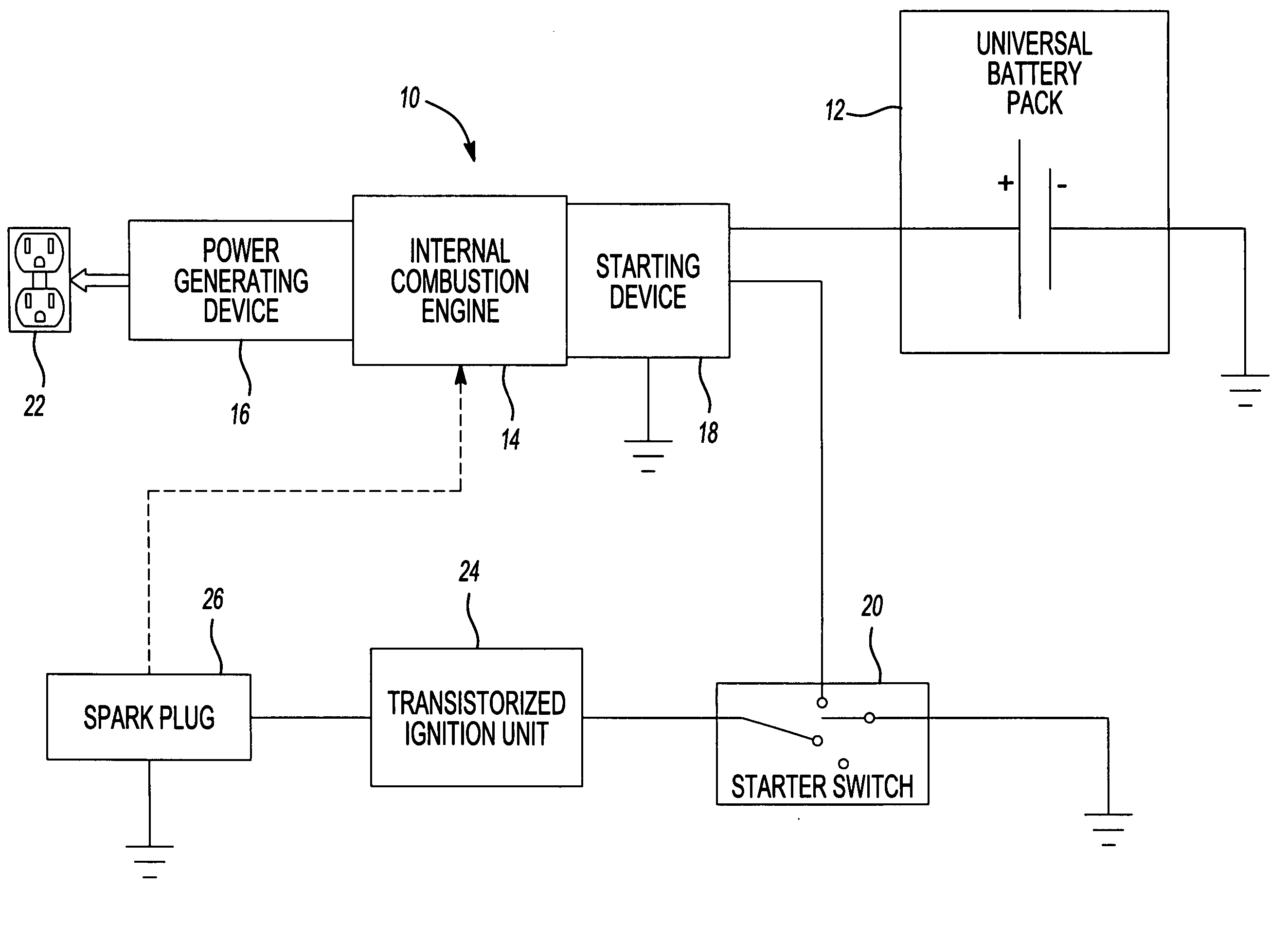
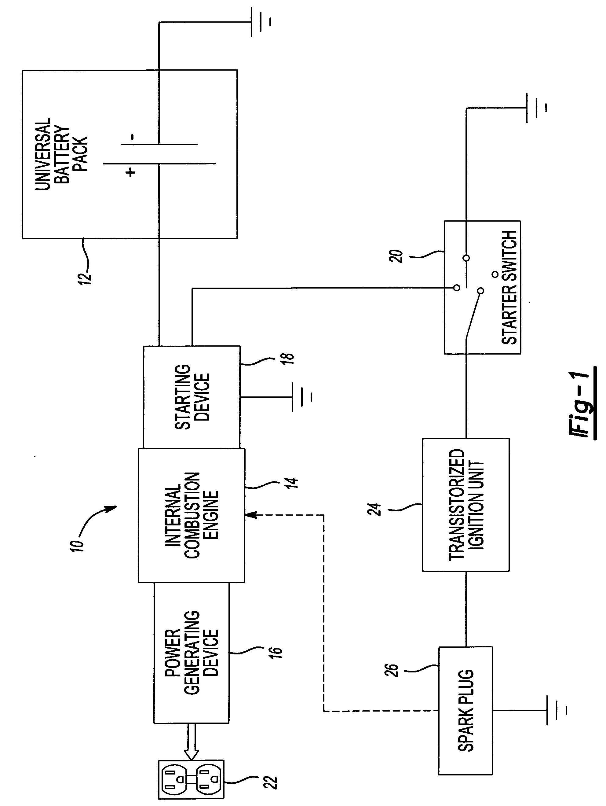
[0039]FIG. 1 is a simplified block diagram of a portable generator system 10, in accordance with an embodiment of the present invention. The generator system 10 utilizes a portable universal battery pack 12 to start an internal combustion (IC) engine 14 that turns a power generating device 16. System 10 additionally includes a starting device 18 connected to universal battery pack 12 and a starter switch 20. Starter switch 20 is connected to a transistorized ignition unit 24, which is in turn connected to a spark plug 26. Starting device 18 is used to turn IC engine 14 at a rate sufficient to start IC engine 14. Once IC engine 14 is started, IC engine 14 drives power generating device 16, whereby power generating device 16 outputs AC power usable by a load connected to an electrical outlet 22.

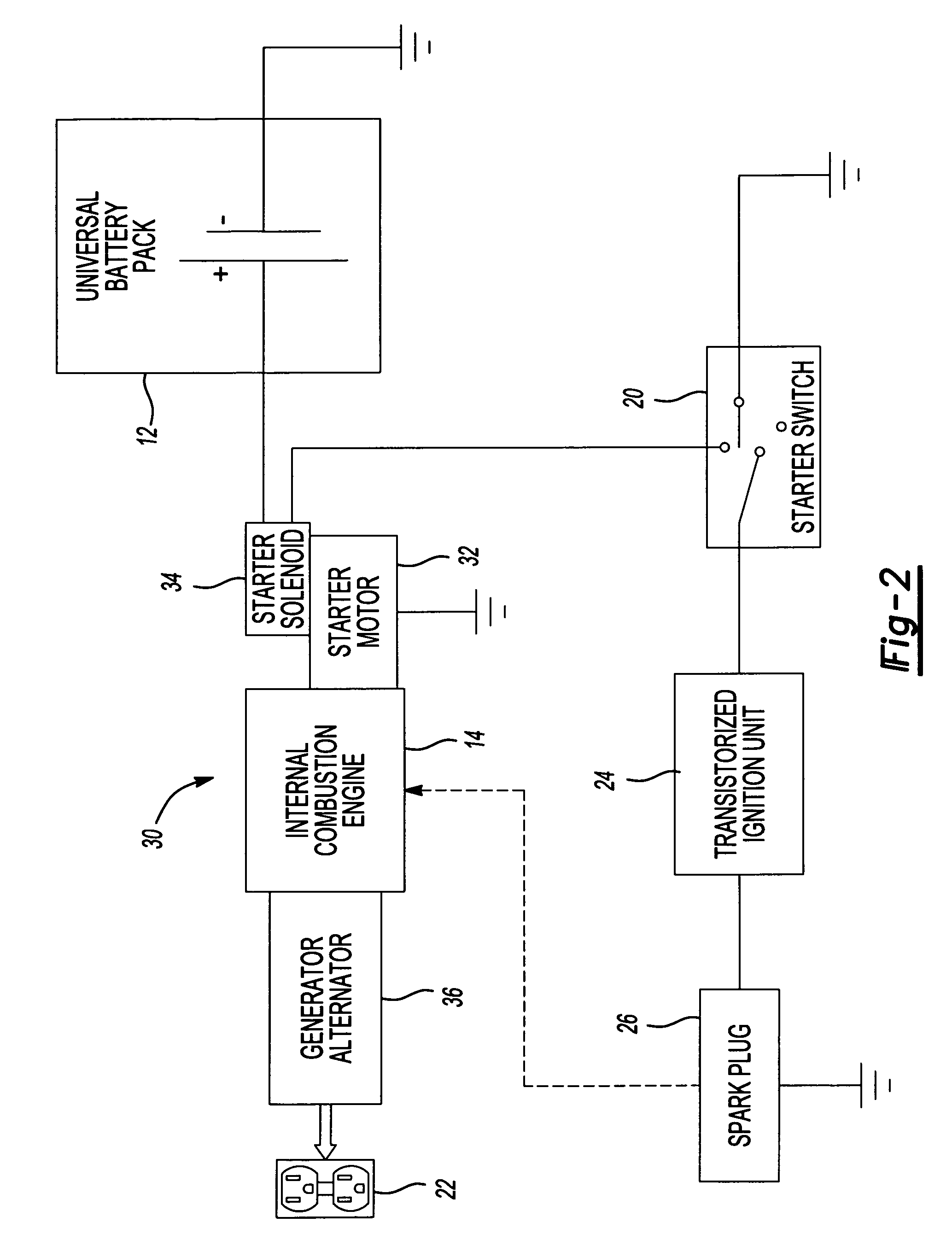
[0040]FIG. 2 is a simpl...


PUM


Abstract

A portable power driven system has a manually movable frame. In one example, an internal combustion engine and a generator device that generates AC power are supported on the frame. The internal combustion engine drives the generator device. An electrically powered starting device is coupled to the internal combustion engine. A control panel is coupled to the frame and includes at least one AC outlet and a battery receptacle that is electrically coupled to the starting device. The battery receptacle is materially the same as a foot of a cordless power tool that receives a battery pack. According to one aspect, the battery pack for the cordless power tool may be permanently mounted in the battery receptacle and provides electrical power to the starting device. The battery receptacle may be contained in an enclosure. The enclosure may provide biasing members urging the battery pack into the battery receptacle.

Description

CROSS-REFERENCE TO RELATED APPLICATIONS [0001] The present application is a continuation-in-part of U.S. patent application Ser. No. U.S. patent application Ser. No. 11 / 321,773 filed Dec. 29, 2005, which is a continuation-in-part of U.S. patent application Ser. No. 10 / 453,988 filed Jun. 4, 2003, which claims the benefit of U.S. Provisional Application No. 60 / 386,904 filed Jun. 6, 2002. The present application also claims the benefit of co-pending U.S. Provisional Application No. 60 / 727,201 filed Oct. 14, 2005 as does U.S. patent application Ser. No. 11 / 321,773. The disclosures of the above applications are incorporated herein by reference.FIELD OF THE INVENTION [0002] This invention relates generally to electrical power generators. More particularly, the invention relates to a system for utilizing a removable, portable universal battery pack and a permanent magnet generator (PMG) to start an internal combustion (IC) engine of the generator. BACKGROUND OF THE INVENTION [0003] Present...

Claims


Application Information

Patent Timeline
Patent Type & Authority Applications(United States)
IPC IPC(8): H02K7/18F02B63/04
CPCF02B63/04F02D29/06F02N11/00F02N11/04F02N11/12H02K7/1815F02N11/0862F02N2011/0888
Inventor GRANT, JEFFREY P.FORSTER, MICHAEL K.
Owner BLACK & DECKER INC
Learn More