
Antenna structure and radio-controlled timepiece

a technology of radio-controlled timepieces and antennas, applied in the direction of non-resonant long antennas, instruments, horology, etc., can solve the problems of inability to make a size of the antenna too small, loss of portability, compactness, thinness, etc., and achieve good radio signal receiving performan

Active Publication Date: 2007-05-31
CITIZEN WATCH CO LTD
View PDF9 Cites 27 Cited by
  • Summary
  • Abstract
  • Description
  • Claims
  • Application Information

AI Technical Summary

Benefits of technology

[0036] Accordingly, an object of the present invention is to solve the above-noted problems of the past, by providing an antenna structure usable in a metal outer case, which provides good radio signal receiving performance without the imposition of restrictions with regard to materials and design, and a radio-controlled timepiece using the antenna structure.
[0037] Another object is to provide an antenna apparatus of a wristwatch, which, when the present invention is applied to a wristwatch, in addition to achieving the above-noted object, prevents an increase in the thickness of the wristwatch and provides an attractive appearance when worn on the wrist.

Problems solved by technology

Specifically, there is the problem of how to improve the antenna receiving performance and also the restriction in designing with regard to size and design because of the placement of the antenna inside or on part of the outer case of the wristwatch.
In particular the antenna, which greatly influences the performance of receiving a radio signal, has a size that is considerable larger than the other components of wristwatches of the past and further, since a placement of the antenna is restricted with respect to the receiving performance thereof, various methods were used, such as internal mounting, external mounting, extendable / retractable mounting, or cord-type mounting.
With this type of receiving antenna, because the output of the receiving antenna is approximately proportional to the size of the receiving antenna, it is not possible to make a size of the antenna too small in order to obtain practically usable receiving performance.
Accordingly, there are problems in selecting a material or in positioning of a member used in a place or in the vicinity of the antenna so that the receiving characteristic should not be reduced in the case of a compact wristwatch.
Because a non-metal such as plastic or the like was used in order that the antenna case does not cause a decrease in receiving performance, there was a large protrusion, so that not only were compactness, thinness, and portability lost, but also there was a prominent loss in the degree of freedom of design.
Also, in the case of an internal receiving antenna, although ceramic or plastic is used as a material for the outer case (bottom cover part and side parts) of the wrist watch in order not to reduce the receiving performance, because these materials have little strength, the thickness thereof increases, thereby causing a loss of housing capacity and portability, and also greatly restricting design, resulting in a wrist watch that is lack of high quality feeling with massive feeling in its appearance.
However, in a configuration in which the antenna is disposed in the band, because the antenna exists inside the band, it is necessary to make electrical connection with the electronic apparatus, and it is not possible to impart sufficient flexibility to the connection part between the two.
Additionally, it is not possible to use a band of metal, which would interfere with radio waves, and it is necessary to use a band of rubber or the like, this presenting a restriction in terms of materials and design.
In a configuration in which the antenna is mounted on the upper surface or side surface of a wrist watch because the antenna is at a distance from the metal part of the wrist watch itself, there is an increase in the thickness or size of the overall watch, thereby causing a problem of a design restriction.
Additionally, in the instance in European patent 0382130, in which the antenna is disposed in a ring shape on the upper surface of the case, because reception is not possible if metal exists within the ring, there is the problem of the practical necessity to provide antenna that is separate from the watch.
Additionally, although in Japanese Unexamined Patent Publication No. 11-64547 there is a disclosure of a wristwatch in which a coil is disposed in a channel-shaped depression provided around the periphery of a circuit board and in which a core is disposed in a curve along the circumferential direction of the circuit board, in addition thereto the manufacturing process thereof is made complex, and further the assembly process in the manufacturing process also becomes complicated leading it troublesome.
In the above-noted prior example, however, because glass or ceramic is used, there is the problem that the thickness of the watch increases.
Also, because either a large sized high-sensitivity antenna structure was used or usage thereof was limited to an area in which the radio signal field strength was high, the convenience of the radio-controlled timepiece is suffered.
Furthermore, in a wristwatch having this configuration, although it was possible to achieve a radio signal that reached the antenna, and the bottom cover part was thinly plated with a metallic plating so as to give the user the impression that metal was actually being used, in terms of outer appearance, there was no feeling of weightiness or textural quality, so that the high-quality image was lost.

Method used


Image

  • Antenna structure and radio-controlled timepiece
  • Antenna structure and radio-controlled timepiece
  • Antenna structure and radio-controlled timepiece

Examples


embodiment 1

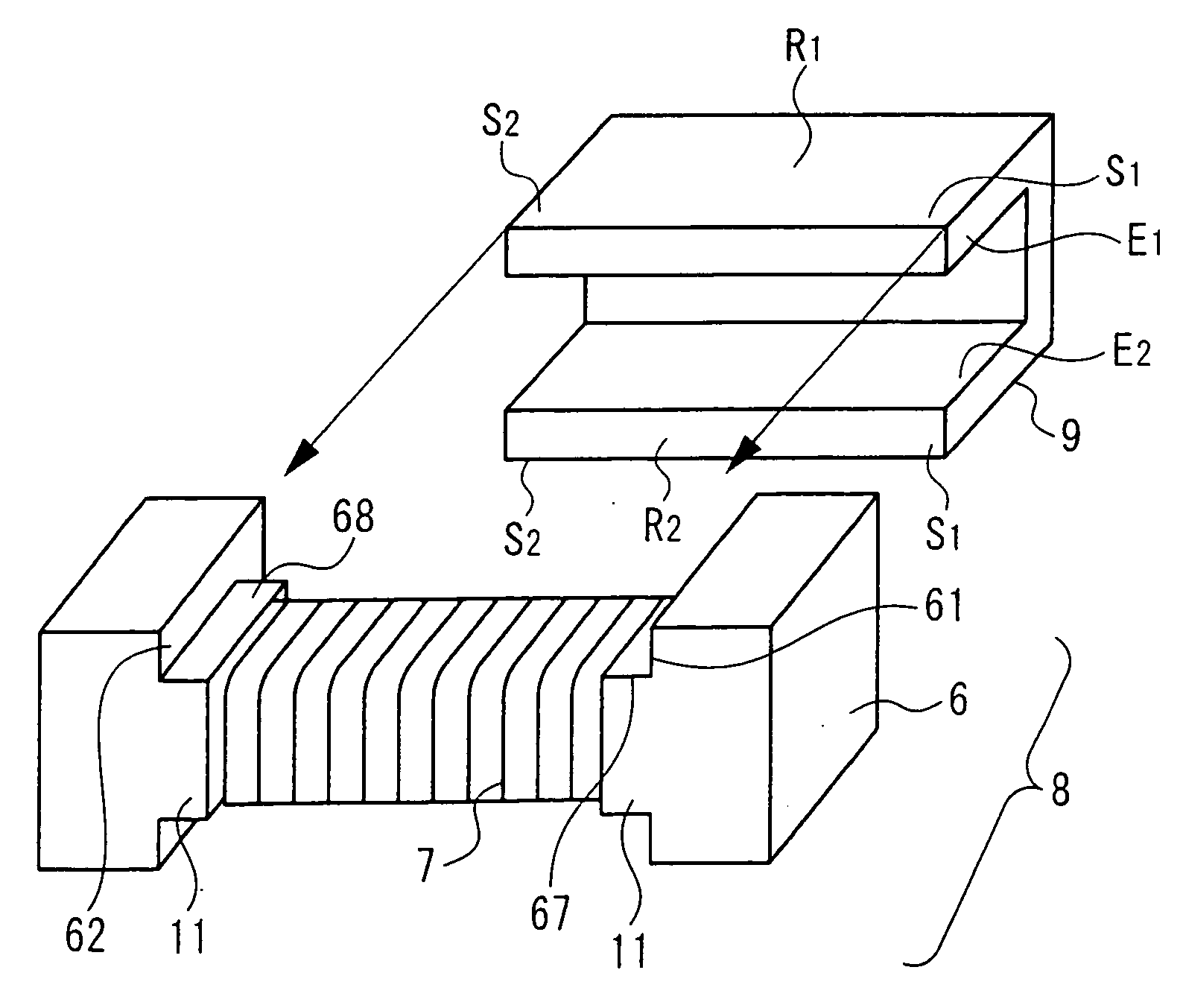
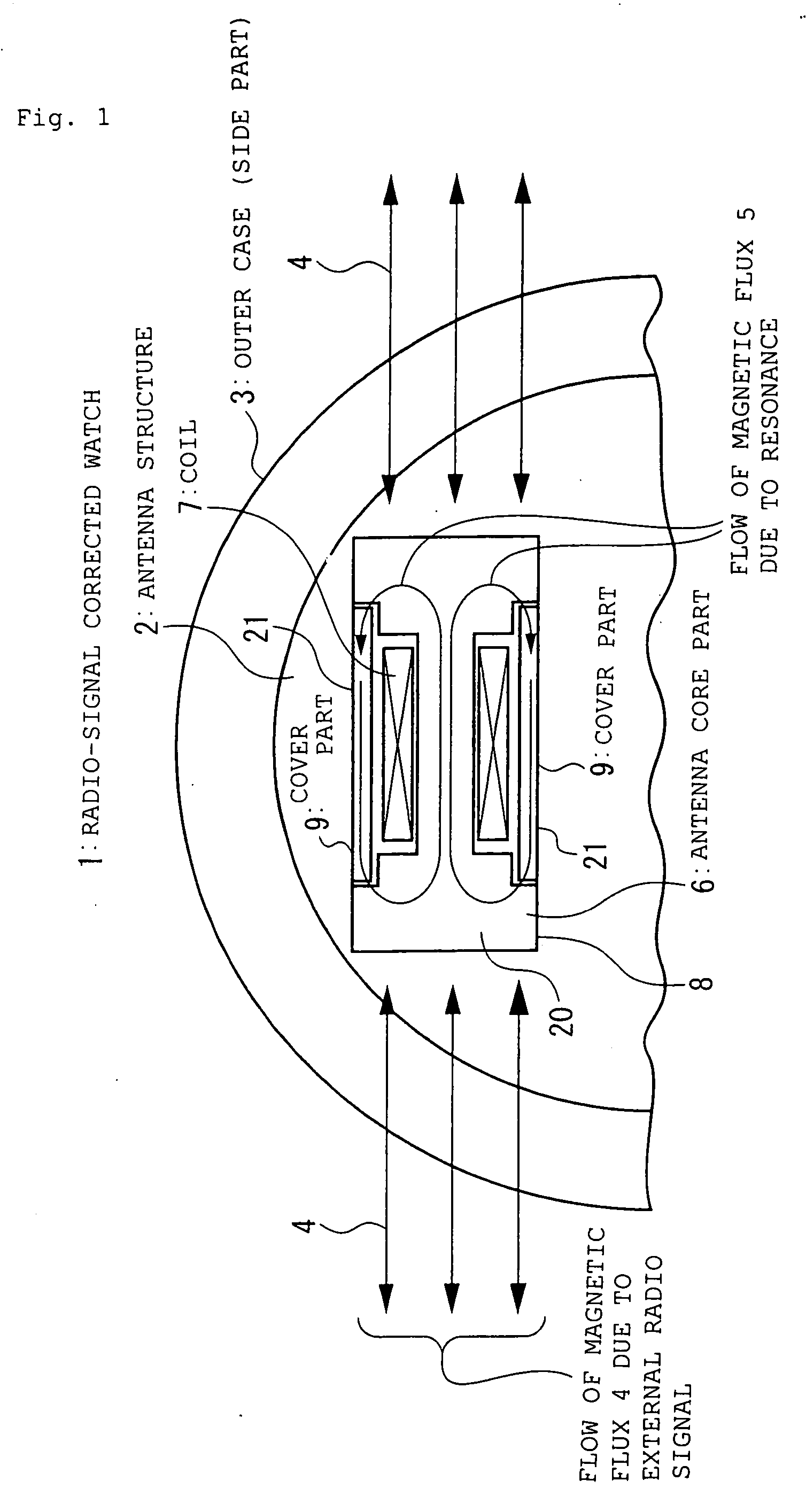
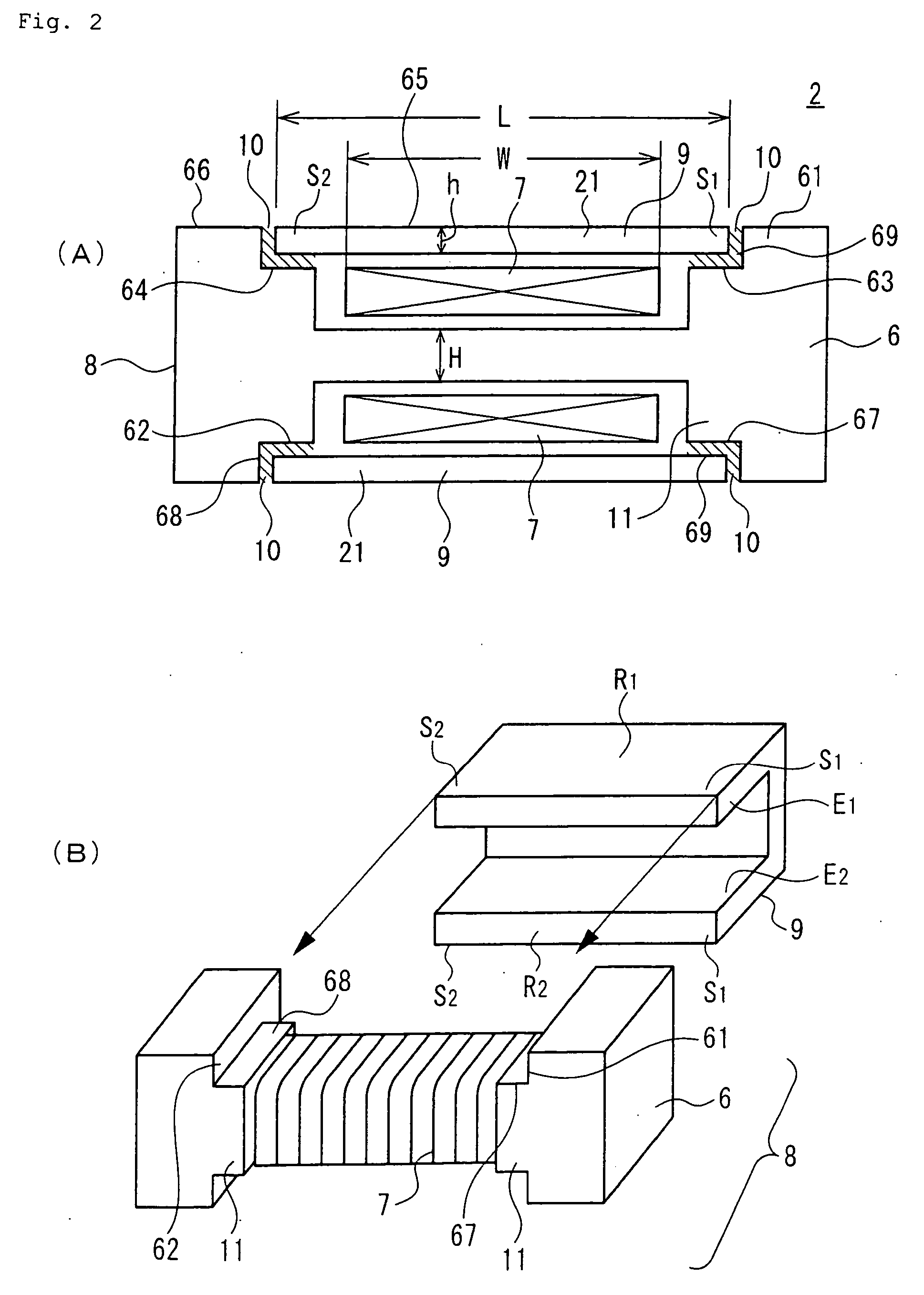
[0063] Specifically, as shown in FIG. 1, the antenna structure 2 according to the first embodiment of the present invention is the antenna structure 2 that, as noted above, is used inside a metal outer case 3 and that receives a radio signal, the antenna structure 2 being formed by an antenna part 8 having an antenna core part 6 made of a soft magnetic material, and a coil part 7 formed by the winding of a conductive wire around the antenna core part 6, and a cover part 9 made of a soft magnetic material covering at least a part of the antenna part 8, the construction being such that, for example, the cover part 9 is joined to the antenna core part 6 via a joining part 10 and the antenna core part 6 and cover part 9 forming a substantially closed magnetic path, so that because the magnetic flux 7 generated at the time of resonance flows through this substantially close magnetic path, it is difficult for the magnetic flux 7 generated by resonance to leak to the outside of the antenna...

embodiment 2

[0185] Next another specific example of the antenna structure 2 according to the present invention is described below.

[0186] Specifically, the antenna structure 2 of this specific example has, for example, collectors 20 and 20′ made of a soft magnetic material, which provide additional collection of a radio signal from the outside, formed at the two end parts 71 and 72 in the longitudinal direction of the antenna core part 6 in the antenna part 8 as shown in FIG. 11.

[0187] The collector 20 can be integrally formed as one with the antenna core part 6 at the outer wall parts of the end parts 71 and 72, and the collector part 20 can also be formed as a separate item from the antenna core part 6, provided so as to be in contact with or in the vicinity of the outer wall part of the end parts 71 and 72.

[0188] It is desirable that the cross-sectional area of the collector part 20 perpendicular to the longitudinal direction be smaller than the cross-sectional area perpendicular to the lo...

embodiment 3

[0197] Next, a third embodiment of the second aspect of the present invention is described below.

[0198] Specifically, a second aspect of the present invention, as shown in FIG. 8, is a radio-controlled timepiece 1 having a reference signal generating means 31 for generating reference signals, a timekeeping means 32 for outputting timekeeping information based on the reference signal, a display means 33 for displaying the time based on the timekeeping information, and a receiving means 34 for receiving a standard radio signal having standard time information, and a time information correction means 35 which corrects the output time information of the timekeeping means based on the received signal from the receiving means 34, and in that the receiving means 34 includes an antenna structure 2 having any of the structures noted above and a receiving circuit.

[0199] It is preferable that the radio-controlled timepiece 1 in this specific example either has an outer case made of a metal m...


PUM


Abstract

An antenna structure capable of receiving an external radio signal has a structure that enables reception of magnetic flux caused by an external radio signal, but has a magnetic path that makes it difficult for magnetic flux generated by resonance to leak to said outside of said antenna structure, said magnetic path being formed minimally by an antenna part, which is formed by at least one antenna core part and a coil part formed by winding of a conductive wire around said antenna core part, and a cover part disposed in a vicinity of said antenna part and covering at least a part of said antenna part, said antenna core part and cover part being made of a soft magnetic material, and also said cover part being joined to said antenna part at both ends of said antenna core part of said antenna part.

Description

BACKGROUND OF THE INVENTION [0001] 1. Field of the Invention [0002] The present invention relates to an antenna structure and to a radio-controlled timepiece that uses the antenna structure, and more particularly it relates to an antenna structure especially for a resonance antenna, which is configured so that even in the case in which the antenna structure is disposed in the vicinity of a metal object, the receiving performance of the antenna structure does not decrease, and to a radio-controlled timepiece that uses the antenna structure as mentioned above. [0003] 2. Related Art [0004] In recent years many wristwatch products using radio signals have appeared. [0005] Specifically, known products include a wristwatch with a radio in which a radio function is added within the wristwatch so as to obtain prescribed information by receiving a broadcasted radio signal, a radio-controlled timepiece that receives a standard radio signal onto which is superimposed a time code so as to autom...

Claims


Application Information

Patent Timeline
IPC IPC(8): H01Q7/08H01Q1/12G04G21/04G04G99/00H01Q1/22H01Q1/27H01Q1/36H01Q1/44H01Q11/08
CPCG04G21/04H01Q1/273H01Q1/362H01Q7/08H01Q11/08G04R60/12
Inventor TAKAHASHI, SHIGEYUKI
Owner CITIZEN WATCH CO LTD
Learn More