
Sequence design in a display system

a display system and sequence design technology, applied in the field of sequence design can solve the problems of difficult to change the chromatic nature of the light being used in the display system, the on/off cycle time of high-intensity light sources is very slow, and the effect of reducing artifacts and negative impact on image quality

Inactive Publication Date: 2007-05-31
TEXAS INSTR INC
View PDF8 Cites 46 Cited by
  • Summary
  • Abstract
  • Description
  • Claims
  • Application Information

AI Technical Summary

Benefits of technology

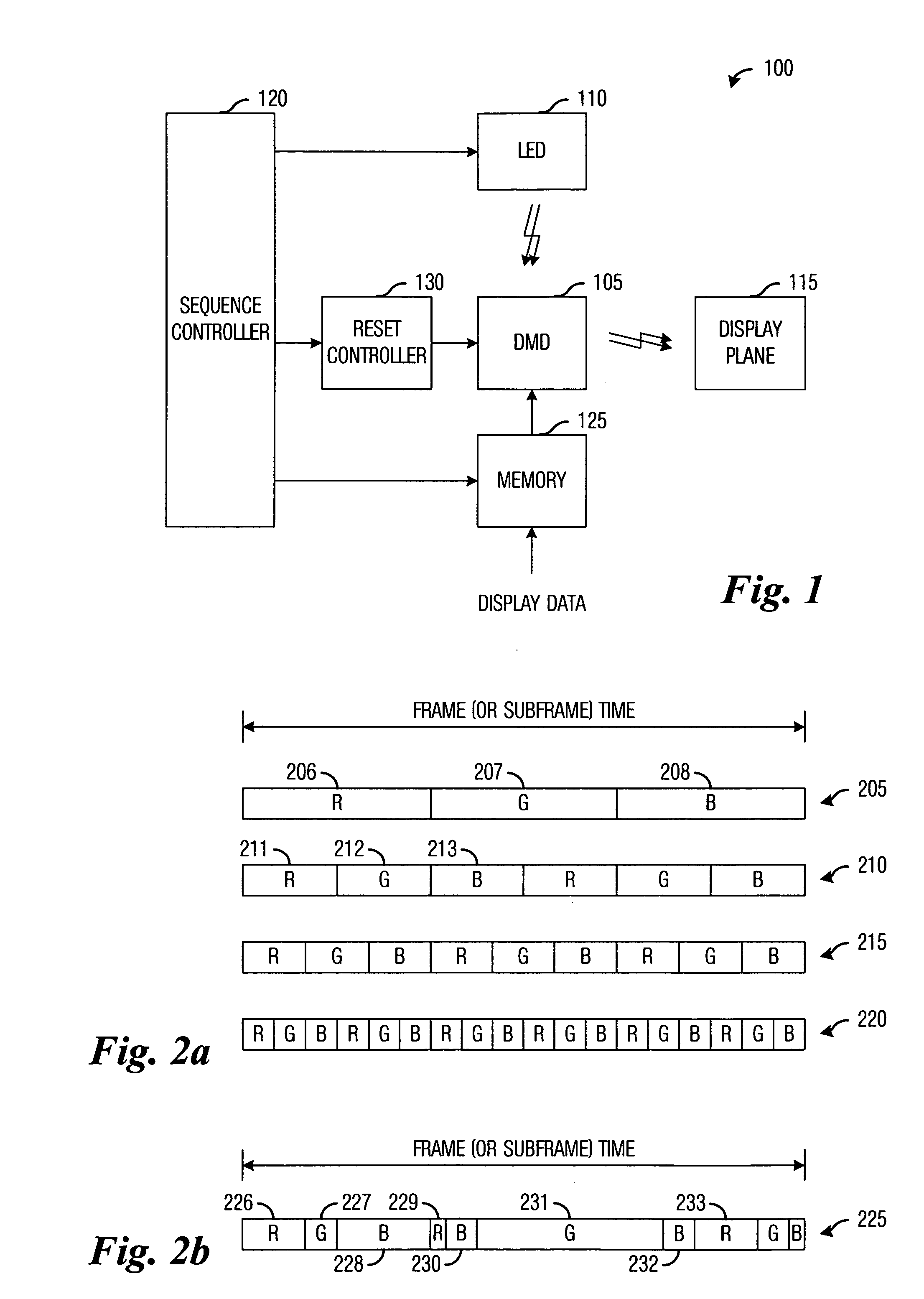
[0009] An advantage of a preferred embodiment of the present invention is that by exploiting the capabilities of the rapidly switching light source, it can be possible to adjust color separation and improve image quality by reducing artifacts, such as transition noise, that can have a negative impact on image quality. For example, color sequences can be optimized to meet display system environmental conditions.
[0010] A further advantage of a preferred embodiment of the present invention is that the distribution of colors being displayed can be changed to alter the color point of the display system. This can allow for adjustment of properties such as white balance, which can change depending upon the environment in which the display system is being used.
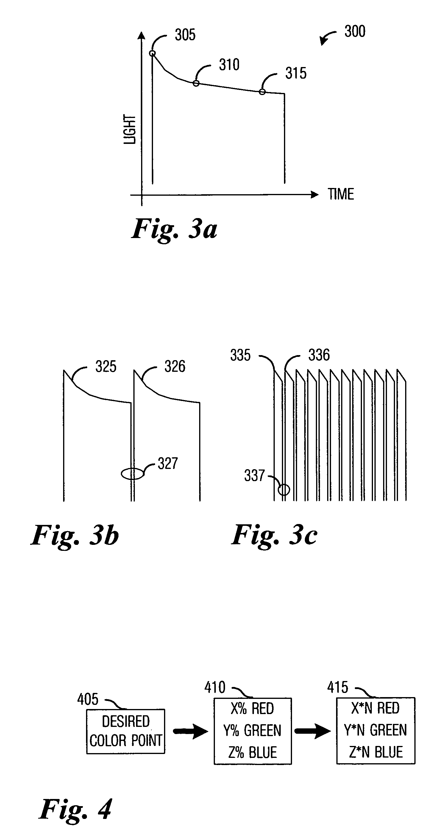
[0011] Yet another advantage of a preferred embodiment of the present invention is that the on time of the rapidly switching light source can be adjusted to maximize light output, light source life, or both.

Problems solved by technology

One disadvantage of the prior art is that the high-intensity light sources have very slow on / off cycle times. Therefore, during normal operation, the high-intensity light sources are left in an on state.
Since the segments of the segmented color filter are fixed, it is not possible to dynamically change the amount of time allocated to a given color.
Therefore, it can be difficult to change the chromatic nature of the light being used in the display system to optimize display quality in different environments.
Another disadvantage of the prior art is that the segments in the segmented color filter are fixed, therefore it is not possible to change the order in which colors are being displayed by the display system or a display duration for each color.
Hence, it is not possible to change the display sequence to help reduce some chromatic distortion and artifacts that are visible when certain color combinations are displayed in sequence.
This typically cannot be optimized a priori since it can depend upon the operating environment of the display system or the nature of the images being displayed, for example.

Method used


Image

  • Sequence design in a display system
  • Sequence design in a display system
  • Sequence design in a display system

Examples


Embodiment Construction

[0021] The making and using of the presently preferred embodiments are discussed in detail below. It should be appreciated, however, that the present invention provides many applicable inventive concepts that can be embodied in a wide variety of specific contexts. The specific embodiments discussed are merely illustrative of specific ways to make and use the invention, and do not limit the scope of the invention.

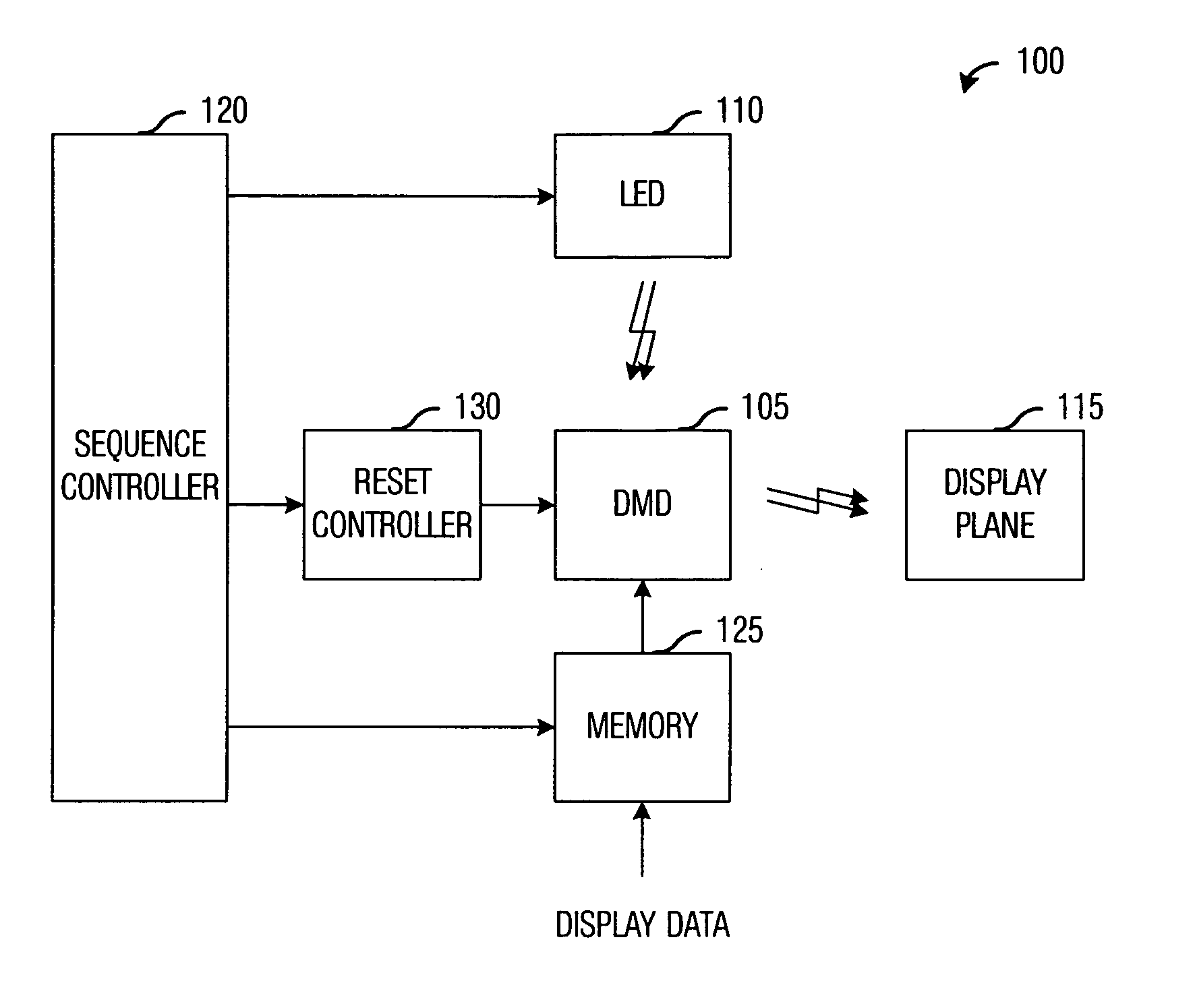
[0022] The present invention will be described with respect to preferred embodiments in a specific context, namely a spatial light modulator (SLM) display system wherein a digital micromirror device (DMD) functions as the SLM and light-emitting diodes (LED) are used as the rapidly switching light source. The invention may also be applied, however, to SLM display systems that make use of alternate SLM technology, such as liquid crystal displays (LCD), deformable mirrors, micro electrical machine systems (MEMS), liquid crystal on silicon (LCoS), and so forth, as well as SLM d...


PUM


Abstract

Method for designing color display sequences in a display system using rapidly switching light sources. A preferred embodiment comprises determining a number of bit segments in a frame time, determining a color sequence, and specifying a bit sequence from the color sequence. The bits in the bit sequence are delineated by a switching of a rapidly switching light source or a state change of a light modulator. The use of the rapidly switching light source can permit the specification of bits that are shorter than a minimum duration of a state change of the light modulator and the possible elimination of a segmented color filter that can enable adjustments to the color point of the display system to meet changing operating conditions.

Description

TECHNICAL FIELD [0001] The present invention relates generally to a method for display systems, and more particularly to a method for designing color display sequences in a display system using rapidly switching light sources. BACKGROUND [0002] Many modern display systems make use of a spatial light modulator to modulate light provided by a light source to create images that can be viewed on a display screen. For example, a display system making use of a digital micromirror device (DMD) as the spatial light modulator modulates light reflecting off the micromirrors on the surface of the DMD to create picture elements of images being displayed, while a display system making use of a liquid crystal display (LCD) as the spatial light modulator modulates light passing through the LCD (or reflecting off the surface of the LCD) to create picture elements of images being displayed. [0003] These display systems typically make use of a high-intensity light source, such as electric discharge a...

Claims


Application Information

Patent Timeline
IPC IPC(8): G09G3/34
CPCG09G3/2018G09G3/34G09G3/3413G09G3/346G09G2310/0235G09G2310/061G09G2320/0666
Inventor BELLLS, HAROLD E. IIHEWLETT, GREGORY JAMESSAWYERS, BRYCE DANIEL
Owner TEXAS INSTR INC
Learn More