Droplet ejecting head

a technology of ejecting head and droplet, which is applied in the direction of printing, etc., can solve the problems of atomizer direction limitation, liquid pollution, and damage to piezoelectric devices, and achieve the effect of more assembly error toleran

Inactive Publication Date: 2007-05-31
IND TECH RES INST
View PDF10 Cites 10 Cited by
  • Summary
  • Abstract
  • Description
  • Claims
  • Application Information

AI Technical Summary

Benefits of technology

[0023] In the spraying process of the droplet ejecting head according to the present invention, the liquid in the pressure chamber will not flow back to the fluid channel. That is, the droplet ejecting head of the present invention can eject droplets of high outflow. Moreover, the annular sy

Problems solved by technology

However, in the atomizer, the vibrational energy is scatteringly propagated to all the liquid in the chamber, so that only the liquid on the level can be atomized; therefore, the driving process may result in superfluous energy waste.
In other words, the atomizer has direction limitation in use.
If the liquid and the piezoelectric device cause a chemical reaction, the chemical reaction may result in piezoelectric device damage and the liquid pollution.
In another aspect, the piezoelectric dev

Method used


Image

  • Droplet ejecting head
  • Droplet ejecting head
  • Droplet ejecting head

Examples


Embodiment Construction

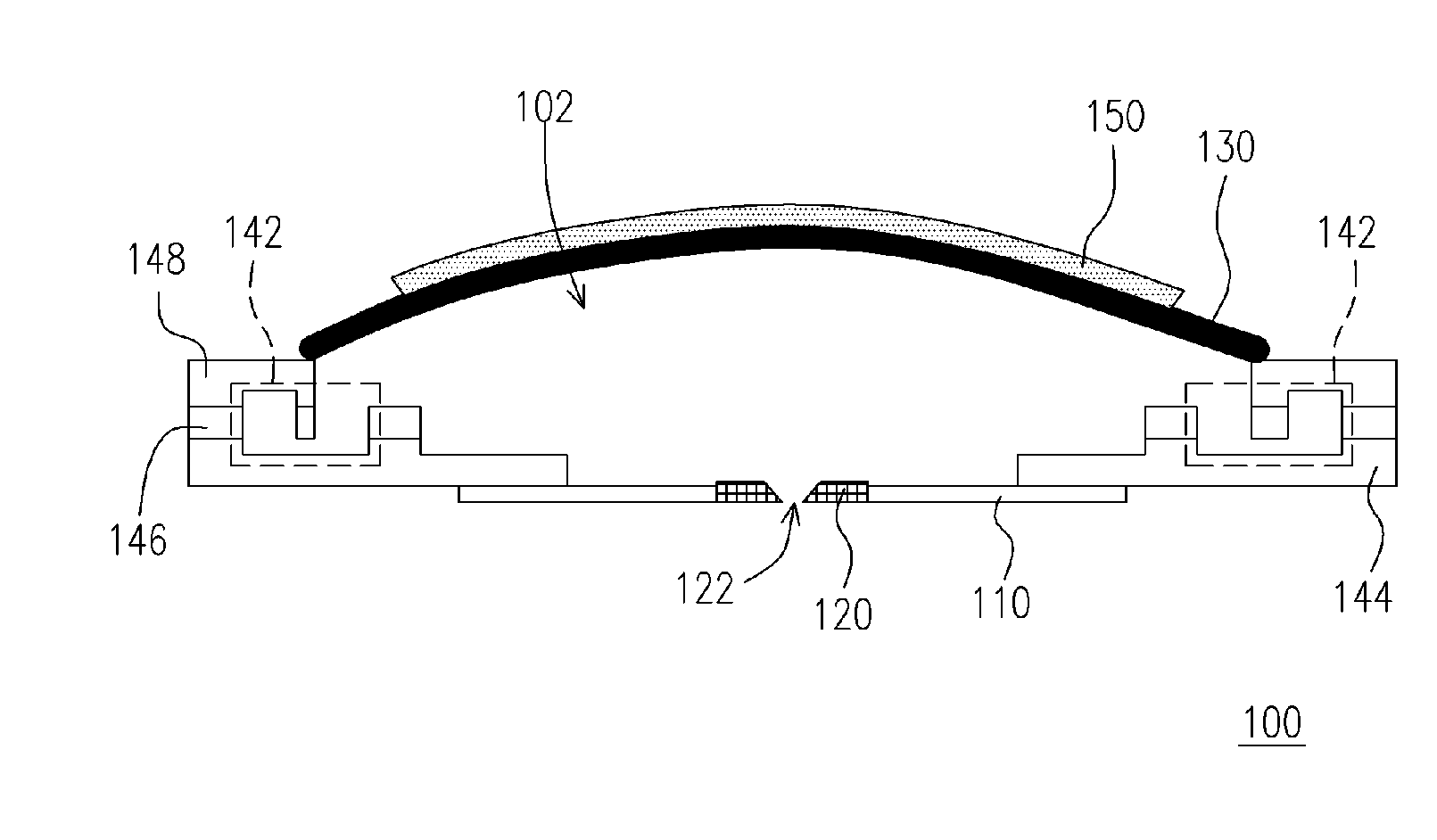
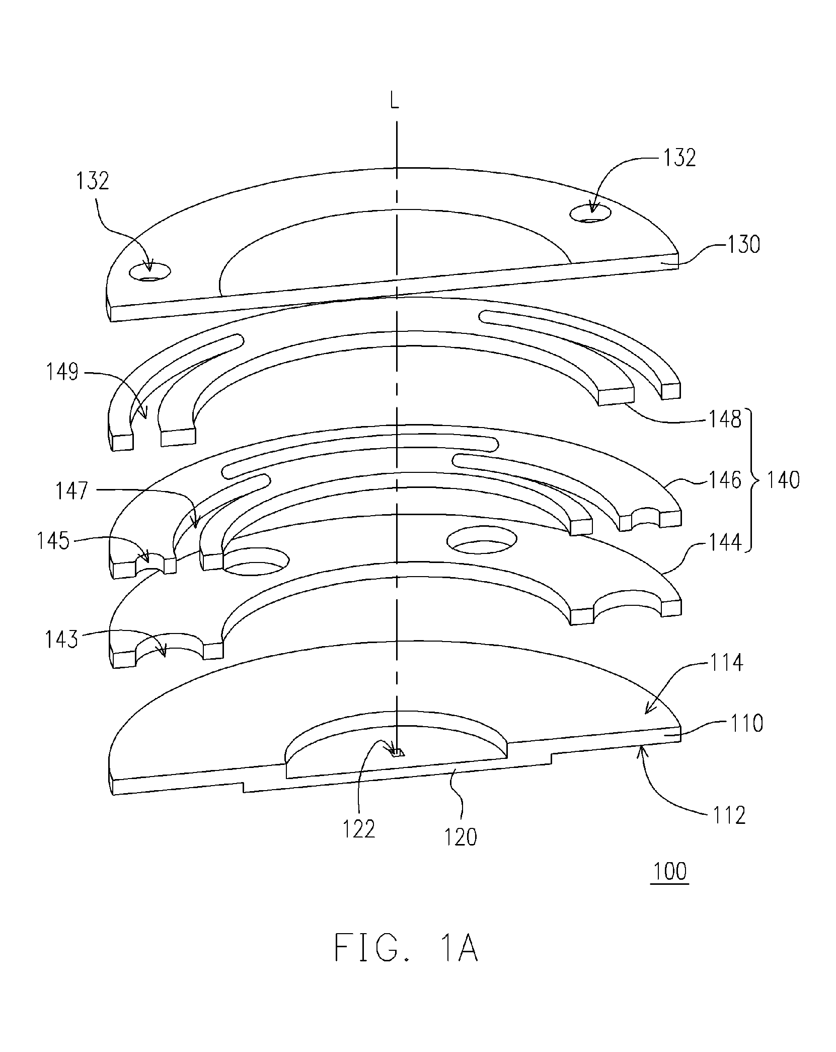
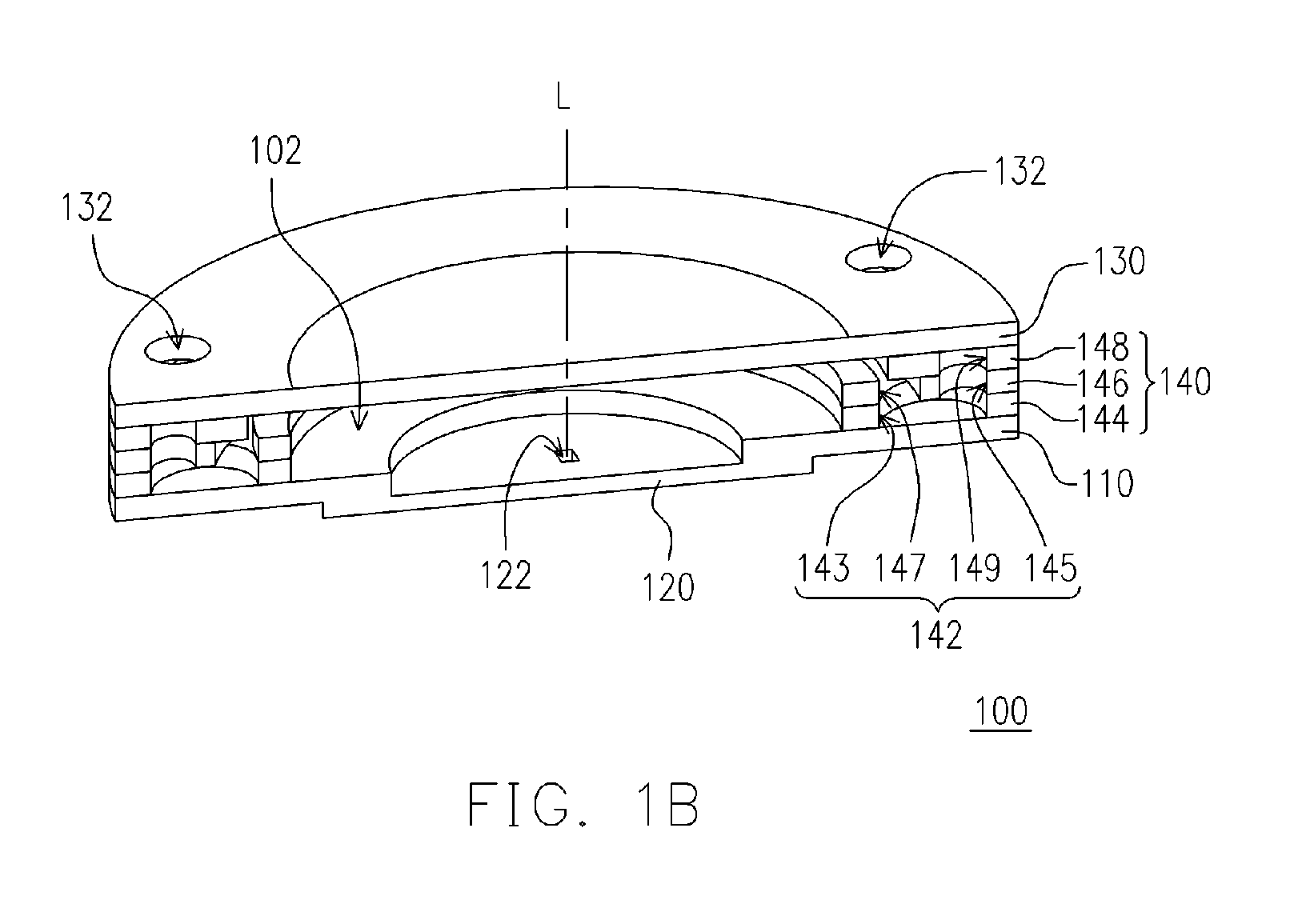
[0035]FIG. 1A is a cross-sectional exploded view of a droplet ejecting head according to one embodiment of the present invention. FIG. 1B is a cross-sectional view of a droplet ejecting head according to one embodiment of the present invention. Referring to FIG. 1A, the droplet ejecting head 100 includes a first substrate 110, a nozzle plate 120, a second substrate 130, an annular symmetrically channel plate 140 and an actuator device 150. Wherein, the nozzle plate 120 with a nozzle 122 is disposed on the first surface 112 of the first substrate 110. The nozzle 122 in the embodiment is, for example, tapered. The second substrate 130 with liquid inlets 132 is disposed over the second surface 114 of the first substrate 110. The liquid (not shown) to be ejected flows to the droplet ejecting head 100 from the liquid inlet 132 of the second substrate 130.

[0036] Note that the medicine solution in current medical industry is usually a mixture of multiple medicine liquids. However, the med...


PUM


Abstract

A droplet ejecting head includes a first substrate, a nozzle plate, a second substrate, an annular symmetrically channel plate and an actuator device. The nozzle plate with a nozzle is disposed on a first surface of the first substrate. The second substrate with a liquid inlet is disposed over the first substrate. The annular symmetrically channel plate with a fluid channel is disposed between the first substrate and the second substrate so that a pressure chamber is formed between the second substrate and the annular symmetrically channel plate. The liquid to be ejected flows to the fluid channel from the liquid inlet and overflows to the pressure chamber from the fluid channel. The actuator device is disposed on the second substrate. The second substrate is deformed by the actuator device for changing volume of the pressure chamber, and then the liquid in the pressure chamber is ejected via the nozzle.

Description

CROSS-REFERENCE TO RELATED APPLICATION [0001] This application claims the priority benefit of Taiwan application serial no. 94141853, filed on November 29, 2005. All disclosure of the Taiwan application is incorporated herein by reference. BACKGROUND OF THE INVENTION [0002] 1 . Field of Invention [0003] The present invention relates to an apparatus for supplying liquid. More particularly, the present invention relates to a droplet ejecting head. [0004] 2 . Description of Related Art [0005] Compared with the conventional atomizer driven by pressure difference, the atomizer using piezoelectric device as driving device has such advantages as quick response, fine structure, portability, micro-size droplet and easy accuracy control etc., so it has been widely applied in medical use, industrial use, engine combustion system, cooling system, and the fabricating process of liquid crystal display, etc. [0006] The U.S. Pat. No. 6,247,525 discloses an atomizer, characterized in using surface w...

Claims


Application Information

Patent Timeline
IPC IPC(8): B41J2/045
CPCB41J2/14
Inventor LU, CHUN-FUCHIANG, HUNG-LIANGYANG, JINN-CHERNGCHEN, CHUN-JUNG
Owner IND TECH RES INST
Why Eureka
Try Eureka