Barring gear assembly for driving in rotation a shaft of a turbo-alternator group

a technology of barring gear and rotating shaft, which is applied in the direction of wind motors, wind motor components, motors, etc., can solve the problems of high maintenance costs, long and complex adjustment operations, and clumps on the shaft, so as to improve accessibility, reduce bulk, and facilitate maintenance

Active Publication Date: 2013-09-19
GENERAL ELECTRIC TECH GMBH
View PDF4 Cites 3 Cited by
  • Summary
  • Abstract
  • Description
  • Claims
  • Application Information

AI Technical Summary

Benefits of technology

[0008]The object of the present invention is to rectify these disadvantages by improving accessibility, making maintenance easy, reducing bulk and simplifying equipment.

Problems solved by technology

Such an arrangement has a certain number of disadvantages:the presence of the clutch on the shaft makes maintenance operations of the barring gear assembly highly complex.
This especially implies long and complex adjustment operations as each component is reassembled.
In particular, the presence of the clutch on the shaft disallows positioning of the barring gear assembly between two rotors of the shaft.the flexible coupling between the hydraulic coupler and the endless screw placed inside the box are subjected to the atmosphere caused by oil projections and oil vapour.
Its shelf life is thus seriously shortened.accessibility to the clutch is very difficult,the arrangement is not optimal.

Method used


Image

  • Barring gear assembly for driving in rotation a shaft of a turbo-alternator group
  • Barring gear assembly for driving in rotation a shaft of a turbo-alternator group
  • Barring gear assembly for driving in rotation a shaft of a turbo-alternator group

Examples


Embodiment Construction

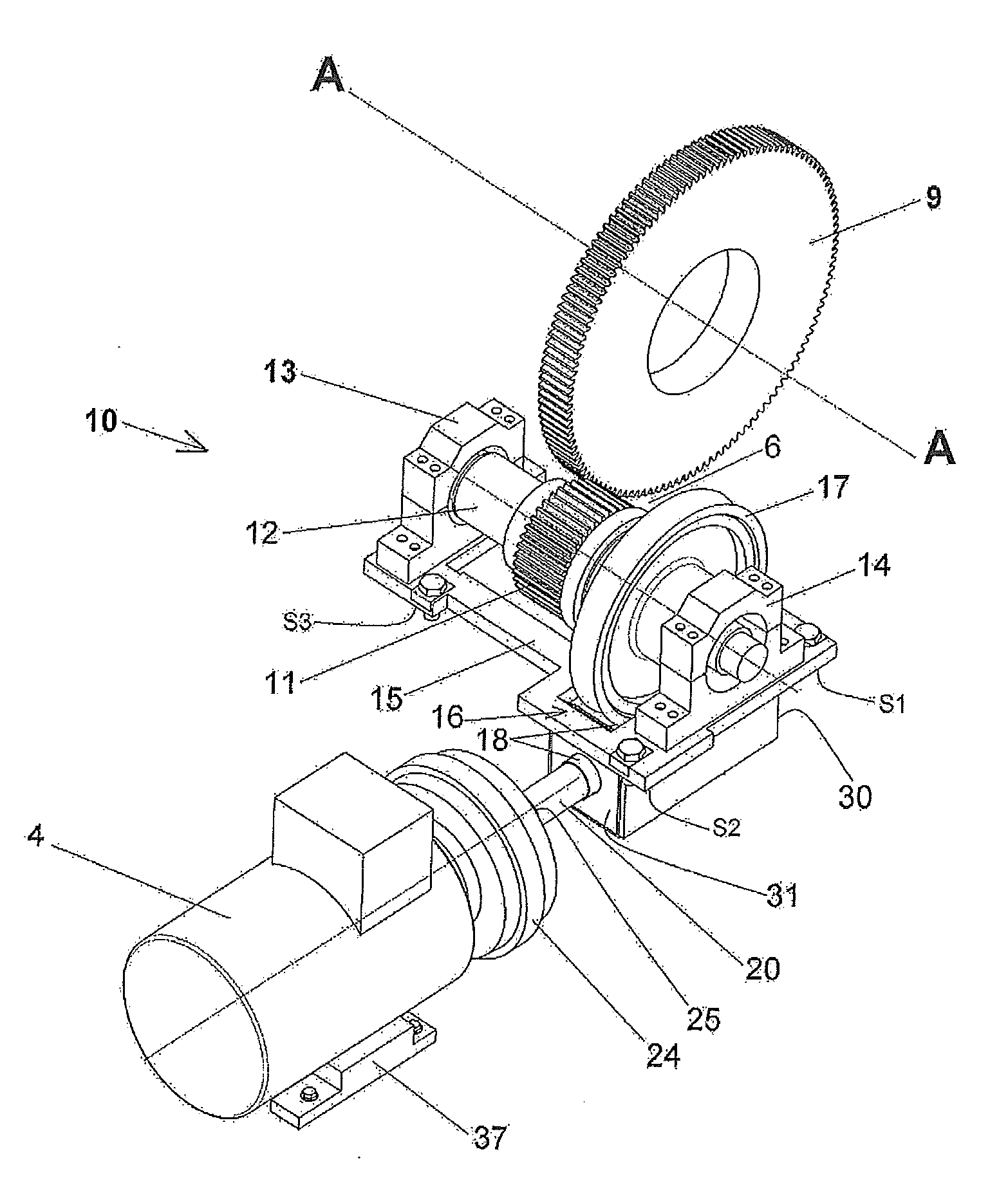
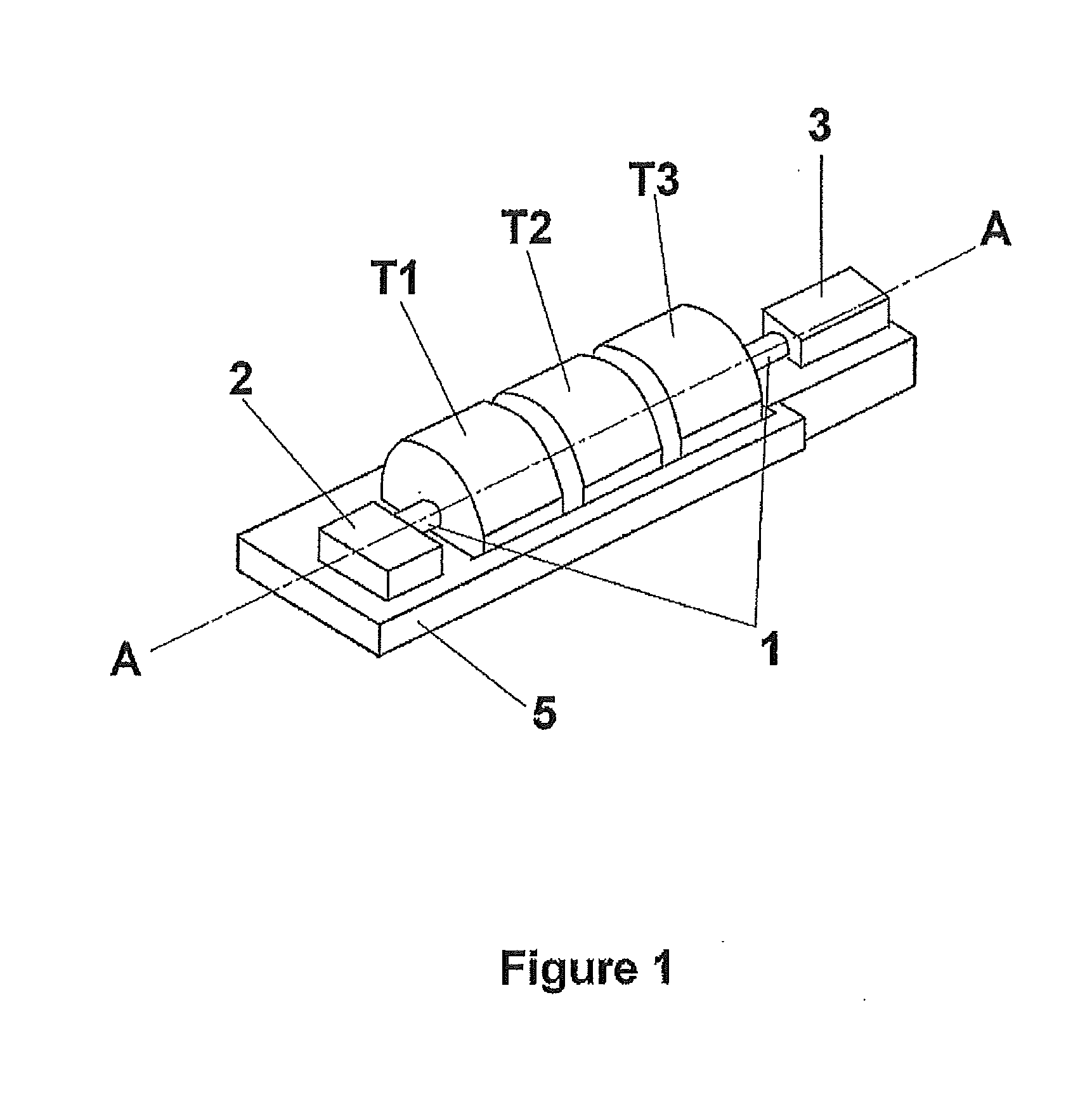
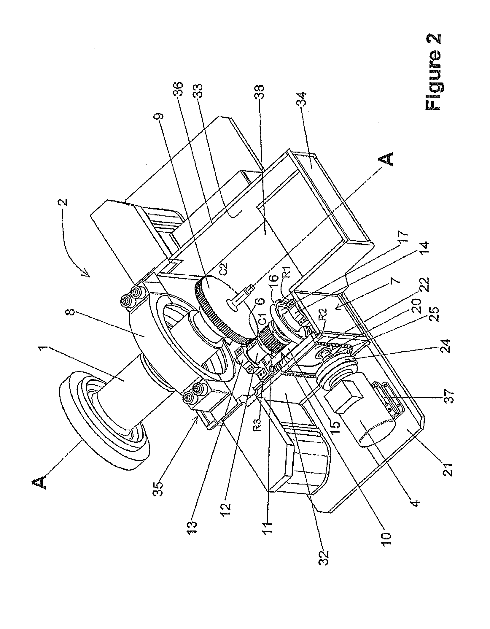
[0025]FIG. 1 illustrates a turbo-alternator group for producing electricity comprising an assembly of steam turbine modules, in this case three turbine modules T1, T2, T3, driving a steam generator 3. This turbo-alternator group rests on a rigid structural frame 5, generally made of concrete. In the present case, the power produced is between 500 MW and 2000 MW. The rotors of the modules of the steam turbine drive the generator 3 in rotation about the axis A. The generator is located to the rear of the turbo-alternator group. The shaft is extended to the front, at its end opposite the generator 3, as far as the barring gear assembly 2. By means of an auxiliary motor 4, the barring gear assembly 2 drives in rotation the shaft 1 via a clutch system 6 which connects or disconnects the shaft 1 to or from the motor 4. During electricity production, the turbine is disconnected from the motor. The motor 4 is preferably electric. According to the invention, the barring gear assembly can als...


PUM


Abstract

The barring gear assembly is designed to drive in rotation a shaft of a turbo-alternator group having an axis of rotation A. The barring gear assembly includes a main wheel fixed on said shaft and defining lateral sides located on either side of the axis of rotation A, a barring gear module having a support piece on which is mounted a clutch system for coupling and uncoupling a secondary shaft to and from the main wheel, the secondary shaft being driven by an auxiliary motor, and the barring gear module being positioned on one of said lateral sides (C1) of the axis of rotation A.

Description

TECHNICAL FIELD[0001]The present invention relates to the field of turbo-alternator groups. It focuses in particular on steam turbines but could be applied to gas turbines. Such turbines are used in power plants, each turbine driving a generator producing electricity. This can be a plant operating on fossil or non-conventional energy.[0002]More particularly, the invention relates to a barring gear assembly for driving in rotation a shaft comprising rotors of each module of the turbine as well as that of the generator. Rotation occurs by means of an auxiliary motor capable of overcoming the resistant couple of the shaft. The periods of turning take place during phases preceding or following periods of electricity production of the turbo-alternator group. Rotation of the shaft during startup and stopping periods of the group is necessary in light of homogenising the temperatures of the rotor and thus avoiding any flexion of the shaft under the effect of thermal dissymmetry. The barrin...

Claims


Application Information

Patent Timeline
Patent Type & Authority Applications(United States)
IPC IPC(8): F01D25/34
CPCF01D25/36F01D25/34F05D2260/4031F05D2220/31
Inventor BASTIER, ARNAUDMIZERA, JACQUES
Owner GENERAL ELECTRIC TECH GMBH
Why Eureka
Try Eureka