Display apparatus

a display apparatus and display technology, applied in non-linear optics, instruments, optics, etc., can solve problems such as the thickness of 4 mm, and achieve the effect of reducing the overall size of the display apparatus and thinning the display apparatus

Inactive Publication Date: 2007-05-31
SAMSUNG DISPLAY CO LTD
View PDF5 Cites 13 Cited by
  • Summary
  • Abstract
  • Description
  • Claims
  • Application Information

AI Technical Summary

Benefits of technology

[0007] The present invention provides a thinner display apparatus than has heretofore been achievable. Embodiments of the present invention provide a display apparatus including: a first substrate that is divided into a first region and a second region having a reflection layer pattern. A second substrate includes pixel regions each having a pixel electrode. The reflection l

Problems solved by technology

When an LCD with four substrates is used for a terminal, its thickness may exceed 4 mm, which is c

Method used


Image

  • Display apparatus
  • Display apparatus
  • Display apparatus

Examples


Embodiment Construction

[0021] Reference will now be made in detail to the preferred embodiments of the present invention, examples of which are illustrated in the accompanying drawings. In the drawings, the thicknesses of layers and regions are exaggerated for clarity. Like reference numerals in the drawings denote like elements.

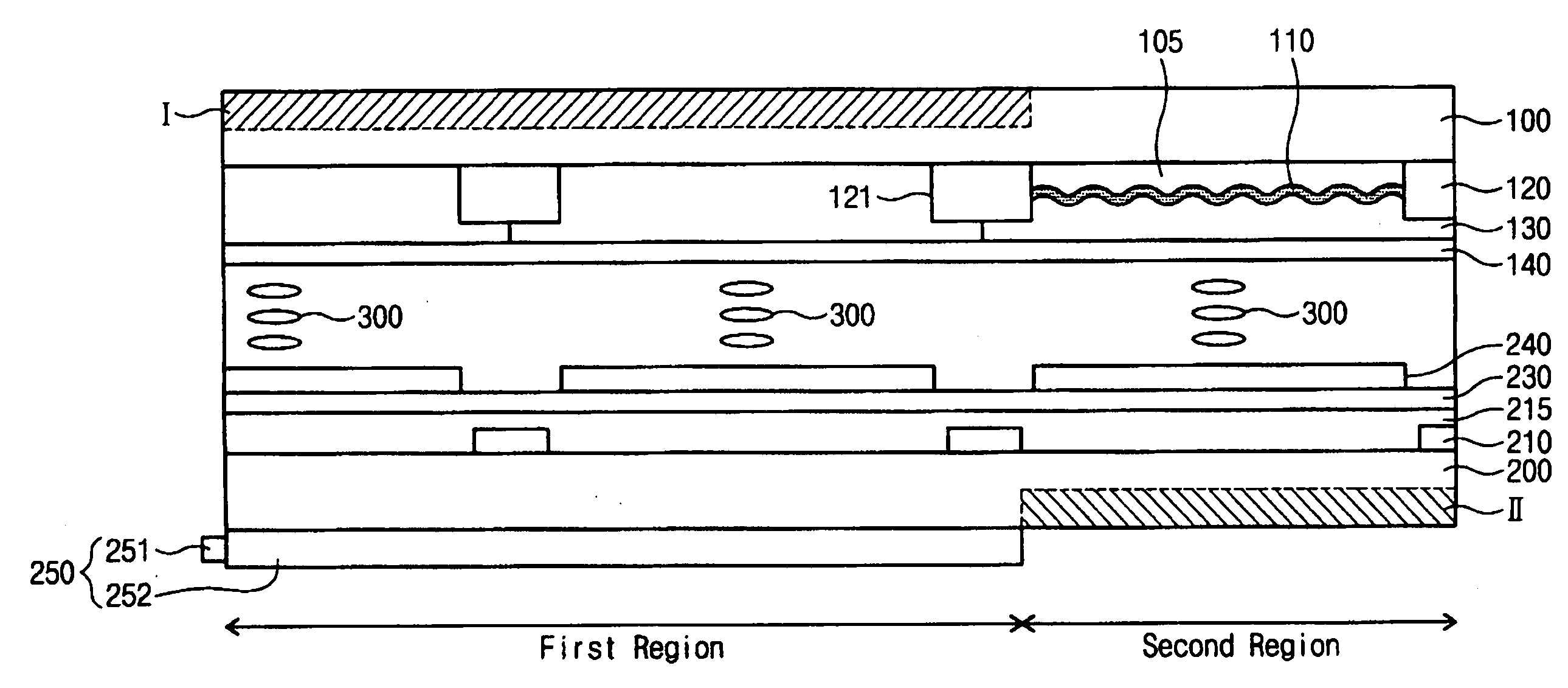
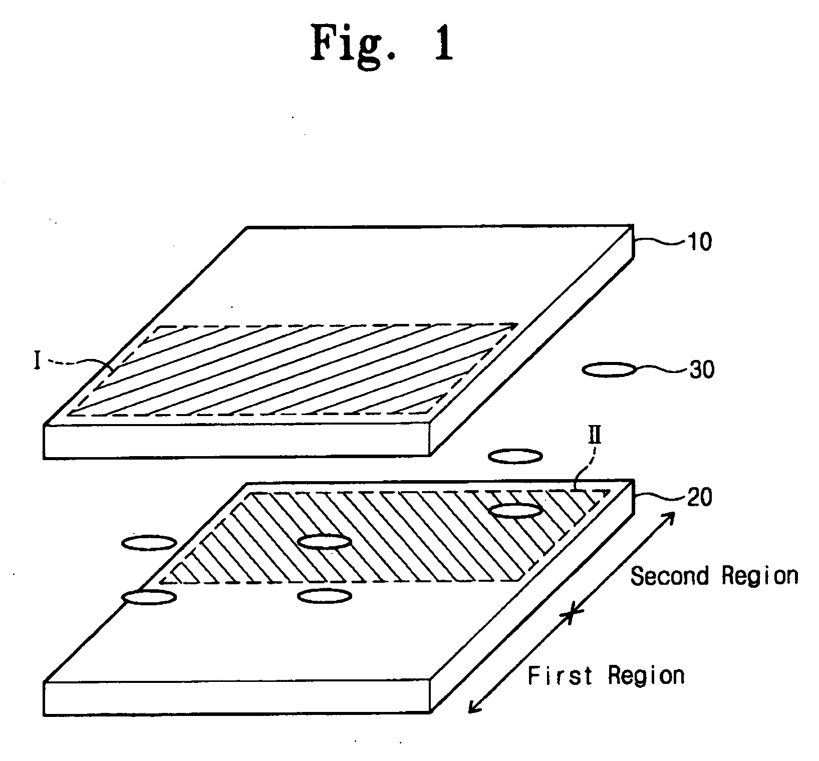
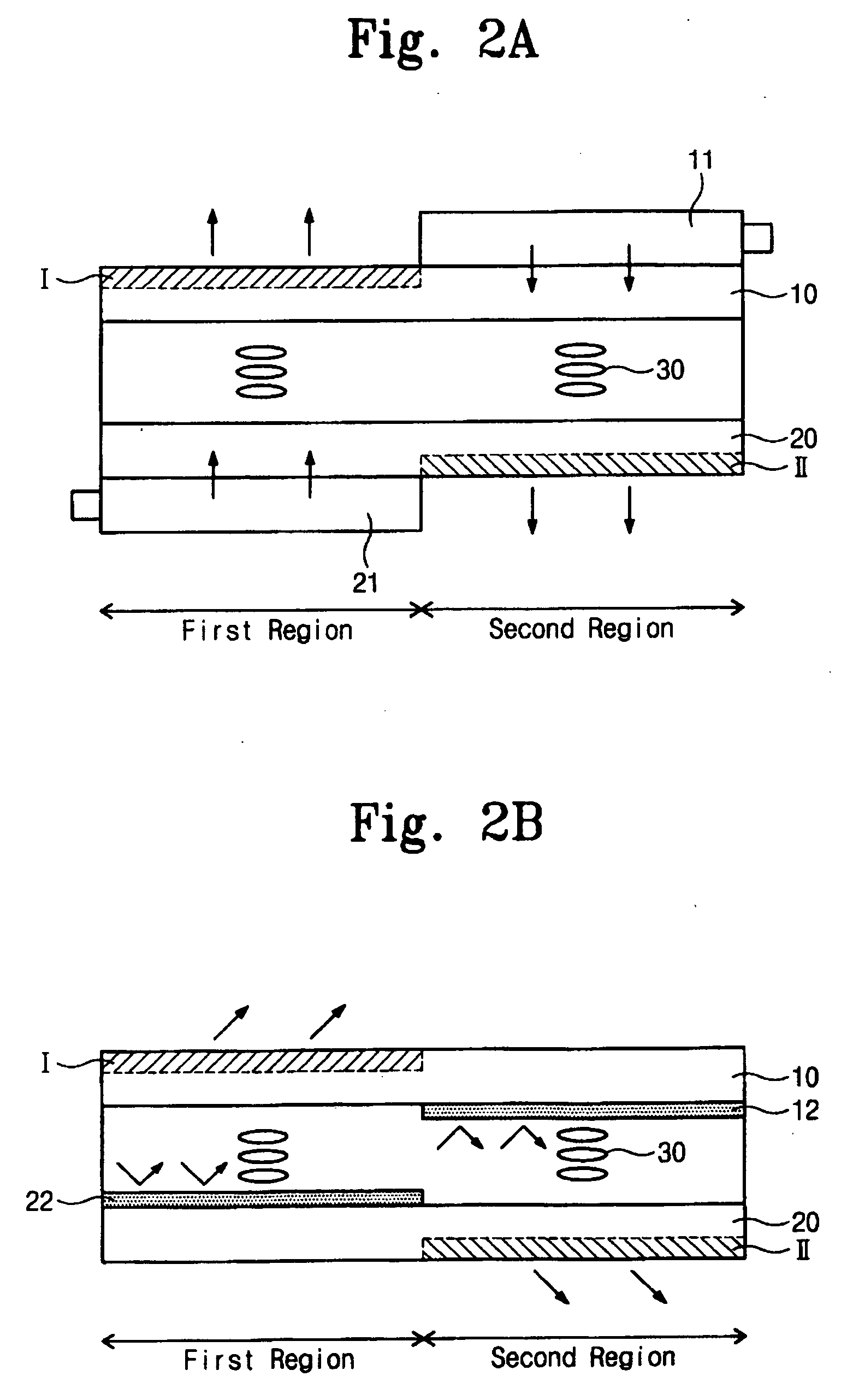
[0022] Referring to FIG. 1, an LCD includes first substrate 10 and second substrate 20 coupled to face each other, liquid crystal (LC) 30 being interposed between them. For convenience, the surfaces of substrates 10 and 20 facing LC 30 are each called an “inside”, the opposite surfaces each being called an “outside”. Also, a display part is a region of an outer surface of the substrates 10 and 20, on which an image is to be displayed.

[0023] Each of the first and second substrates 10 and 20 is divided into a first region and a second region. An image is displayed on a first region (hereinafter referred to as a first display part) formed on outer surface of the first substrate 10....


PUM


Abstract

The display apparatus includes a first substrate and a second substrate. The first substrate is divided into a first region and a second region, and a reflection layer pattern is formed in the second region of the first substrate. The second substrate faces the first substrate. Pixel regions are defined on the second substrate, and a pixel electrode is formed on each of the pixel regions. A transmission type image is displayed on a first region of the first substrate and, on a second region of the second substrate, a reflection type image is displayed, so that a two-sided image is displayed using only two substrates thereby reducing the overall thickness of the display apparatus.

Description

REFERENCE TO RELATED APPLICATION [0001] This application claims the benefit of priority of Patent Application Numbers 2005-113656 and 2005-117519 filed in the Republic of Korea Intellectual Property Office on Nov. 25, 2005 and Dec. 5, 2005. [0002] 1. Field of the Invention [0003] The present invention relates to a display apparatus. [0004] 2. Description of the Related Art [0005] Liquid crystal displays (LCDs) are widely used in desk top and notebook computers as well as in mobile communication terminals. The LCD displays an image when an input electrical signal varies the light transmittance of the liquid crystal that is interposed between two substrates. A backlight assembly is mounted on one of the substrates. Light from the backlight assembly passes through the LC, each pixel displaying a portion of the image determined by the alignment of the adjacent liquid crystal molecules. [0006] Assuming that a place on which the image is displayed is a display part, the display part is fo...

Claims


Application Information

Patent Timeline
IPC IPC(8): G02F1/1335
CPCG02F1/133553G02F2001/133342G02F2001/133391G02F1/133342G02F1/133391
Inventor LEE, HO-JUNGHUR, SE-KANGKIM, JIN-TAKHAN, HO-SEOKLEE, JAE-YOUNG
Owner SAMSUNG DISPLAY CO LTD
Why Eureka
Try Eureka