Projector

Inactive Publication Date: 2007-05-31
COLUMBIA PEAK VENTURES LLC
View PDF10 Cites 9 Cited by
  • Summary
  • Abstract
  • Description
  • Claims
  • Application Information

AI Technical Summary

Benefits of technology

[0012] An advantage of some aspects of the invention is to provide a projector that is able to improve the use efficiency of light both in the desktop mount position and the ceiling suspension position with a light source device that has a smaller size and a simple structure.

Problems solved by technology

Accordingly, it is impossible to effectively apply the luminous flux output from the light source device to the light modulation device, and the use efficiency of light becomes lower.
However, since the projector disclosed in JP-A-8-314010 adopts the structure in which the lamp unit is rotated with the optical axis as the center axis, the operation according to the position of the protector (rotation of the lamp unit) is troublesome.

Method used


Image

  • Projector
  • Projector
  • Projector

Examples


first embodiment

[0056] Hereinafter the first embodiment of the invention will be described based on the drawings.

Configuration of Projector

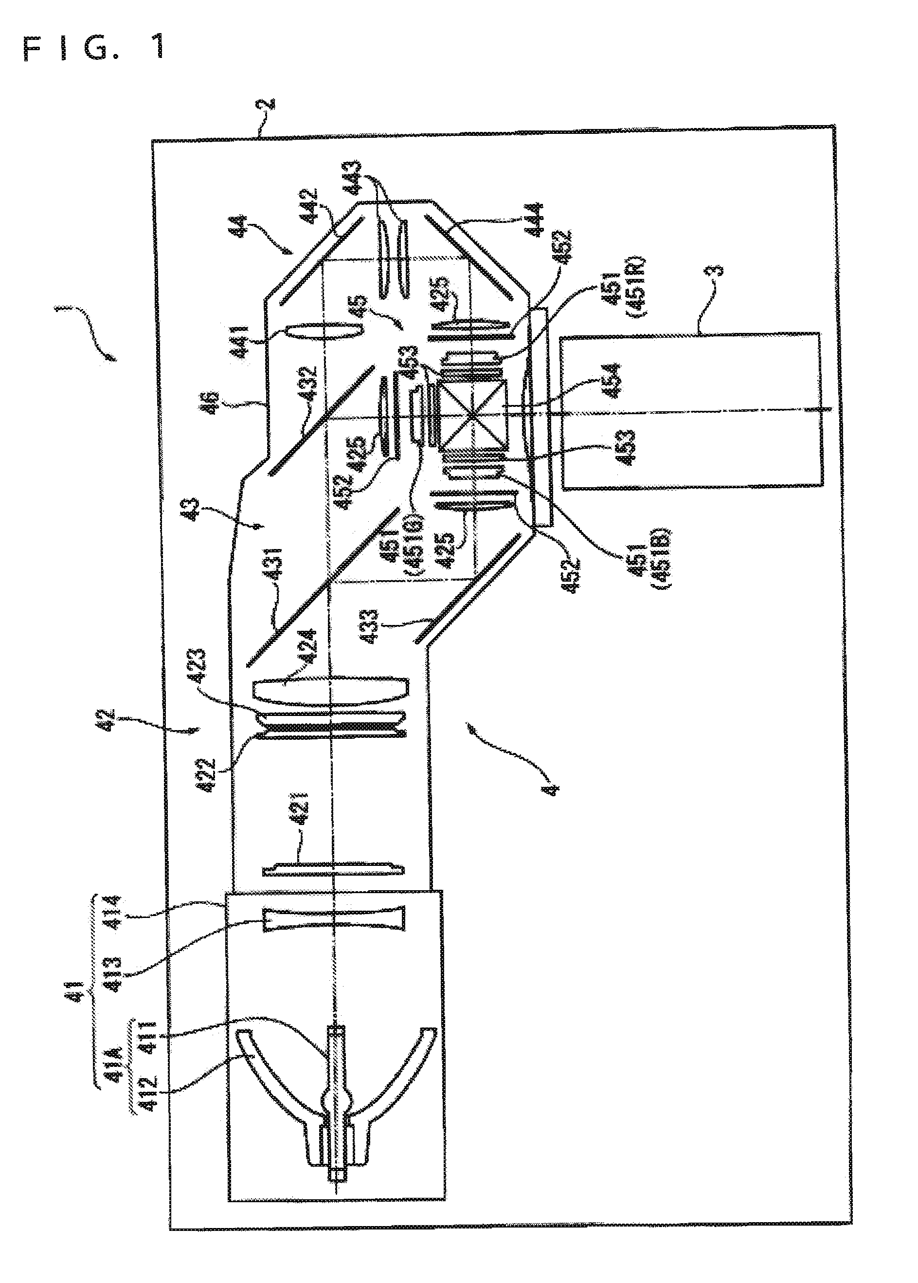
[0057]FIG. 1 schematically shows an outline configuration of a projector 1.

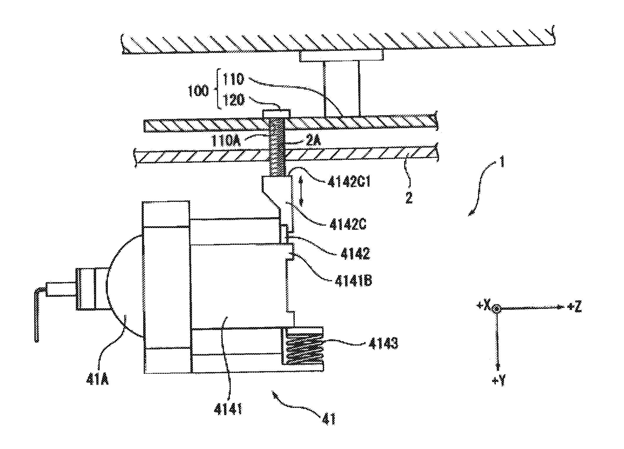
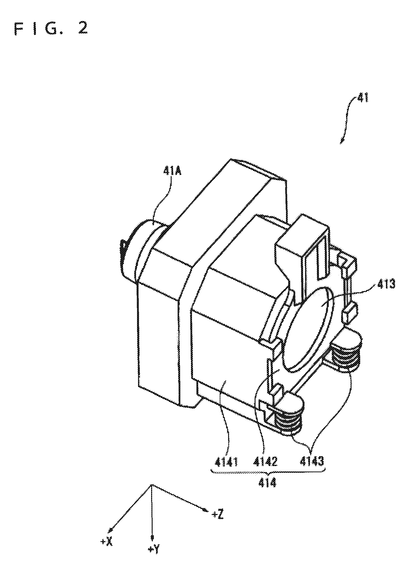
[0058] The projector 1 forms an optical image by modulating a luminous flux output from a light source according to image information and magnifies and projects the formed optical image onto a screen (not shown). In the embodiment, the projector 1 is arranged so as to magnify and project the formed optical image onto a screen (not shown) both in a condition in which the projector 1 is mounted on an installation surface of a desk or the like (desktop mount position) and a condition in which the projector is suspended from an installation surface of a ceiling or the like oppositely in the vertical direction to the desktop mount position (ceiling suspension position.) The projector 1 includes an exterior casing 2, a projection lens 3 as a projection optical device, an optical unit 4, etc...

second embodiment

[0128] Next, the second embodiment of the invention will be described based on the drawings.

[0129] In the description as below, the same signs are assigned to the same structure and the same parts as those in the first embodiment, and the detailed description thereof will be omitted or simplified.

[0130]FIG. 11 is an exploded perspective view showing a configuration of a light source device 51 in the second embodiment. In FIG. 11, as well as in FIGS. 2, 3, and 7, for ease of the explanation, the optical axis of the luminous flux output from the light source device 51 is Z-axis, two axes perpendicular to the Z-axis are X-axis (horizontal axis) and Y-axis (vertical axis), respectively.

[0131] In the first embodiment, the structure in which the parallelizing concave lens 413 is vertically moved according to the position of the projector 1 is adopted.

[0132] On the other hand, in the second embodiment, as shown in FIG. 11, a structure in which, instead of vertical movement of the paral...


PUM


Abstract

A projector includes: a light source device; a light modulation device that modulates a luminous flux output from the light source device; a projection optical device that magnifies and projects the luminous flux modulated in the light modulation device; and an exterior casing that accommodates the light source device, the light modulation device, and the projection optical device arranged within, the projector is arranged so as to be installed in a desktop mount position in which the projector is mounted on a predetermined location and a ceiling suspension position in which the projector is provided opposite in the vertical direction relative to the desktop mount position, the light source device includes a light source device main body having a light source lamp in which discharge emission is performed between a pair of electrodes and an elliptic reflector having a nearly ellipsoidal reflection surface and converging and outputting a luminous flux radiated from the light source lamp in a certain direction, and a parallelizing lens that parallelizes the converged light of the elliptic reflector, and a lens supporting part that supports the parallelizing lens and makes a position of the parallelizing lens relative to the light source device main body changeable according to the position of the projector is provided.

Description

BACKGROUND [0001] 1. Technical Field [0002] The present invention relates to a projector. [0003] 2. Related Art [0004] Previously, a projector including a light source device, a light modulation device that modulates a luminous flux output from the light source device, and a projection optical device that magnifies and projects the modulated luminous flux has been known. [0005] In such a projector, as the light source device, for example, a discharge emission light source device including a light source lamp in which discharge emission is performed between a pair of electrodes and a reflector that aligns and outputs the luminous flux emitted from the light source lamp in a certain direction is often used. In the light source device, the temperature within the light source lamp rises because of heat generation due to light emission and heat convection is caused, a vertical temperature difference is produced within the light source lamp and the gas concentration distribution becomes n...

Claims


Application Information

Patent Timeline
IPC IPC(8): G03B21/20F21Y101/00
CPCH04N9/3141G03B21/2026G03B21/142G03B21/208G03B21/2046
Inventor IINUMA, KAZUYUKIUEHARA, KATSUYUKIUCHIDA, MASAKI
Owner COLUMBIA PEAK VENTURES LLC
Why Eureka
Try Eureka