Optical pick-up actuator

a technology of optical pick-up and actuator, which is applied in the direction of instruments, mountings, data recording, etc., can solve the problems of deteriorating the driving characteristics (such as focusing and tracking), no structure provided to prevent the applied epoxy from flowing to the adjacent structures, and wasting adhesive, so as to prevent the waste of adhesive, eliminate vibration distortion, and uniform movement

Inactive Publication Date: 2007-05-31
LG ELECTRONICS INC
View PDF1 Cites 5 Cited by
  • Summary
  • Abstract
  • Description
  • Claims
  • Application Information

AI Technical Summary

Benefits of technology

[0036] The above-structured optical pick-up actuator allows adhesive for coupling a lens holder to wire springs to be injected accurately into predetermined locations without dripping elsewhere, so that a firmer coupling of the lens holder and the wire springs can be realized, and a fixed amount of adhesive is used, preventing waste of adhesive.
[0037] Also, the damper material that eliminates vibration distortion on the wire springs can be injected quickly and evenly into the filling portions of the wire holder, so that the damping effectiveness of the driving portion has a uniform range of movement, and the assembly process of the optical pick-up actuator becomes simpler.

Problems solved by technology

However, the receiving portion 11a is only stepped, and there is no structure provided to prevent the applied epoxy from flowing to the adjacent structures.
Also, in the process of applying adhesive to the outer surface of the fixing protrusion 11, if the adhesive should drip elsewhere, more adhesive needs to be used in lieu of the dripped adhesive, thereby wasting adhesive.
Additionally, when an excessive amount of adhesive is applied, the weight of the lens holder 2 increases, thereby deteriorating the driving characteristics (such as focusing and tracking) of the lens holder, which focuses light onto a disk.
However, the assembly process of radiating ultraviolet rays onto the damper material 16 to obtain a predetermined viscoelasticity thereof, following the filling of the liquid damper material 16 in the filling hole 14, requires much equipment and manpower.
In addition, the assembly process suffers from the problems of having to quickly inject the filling hole 14 with damper material 16, and non-uniformity in performance of the damper material 16.

Method used


Image

  • Optical pick-up actuator
  • Optical pick-up actuator
  • Optical pick-up actuator

Examples


Embodiment Construction

[0048] Reference will now be made in detail to the preferred embodiments of the present invention, examples of which are illustrated in the accompanying drawings. Wherever possible, the same reference numbers will be used throughout the drawings to refer to the same or like parts.

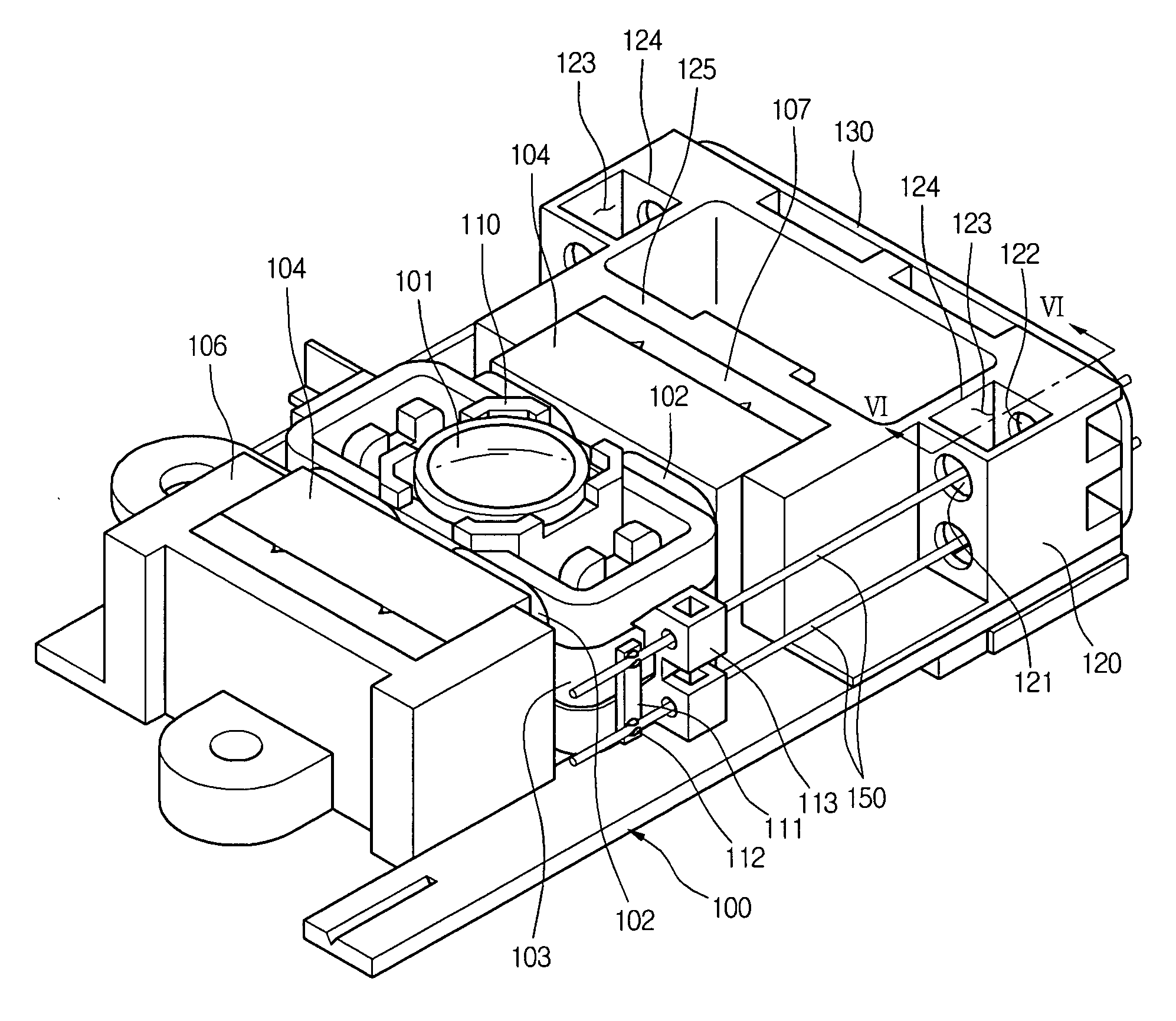
[0049]FIG. 4 is a perspective view of an optical pick-up actuator according to an embodiment of the present invention.

[0050] Referring to FIG. 4, an optical pick-up actuator according to the present invention includes a base 100, a driving portion installed to be supported by the base 100, and a magnetic circuit for prompting the driving portion to be driven in focusing and tracking directions.

[0051] The driving portion is formed of a lens holder 110 with an objective lens 101. The magnetic circuit includes wire-wound focusing and tracking coils 102 and 103 to one side of the lens holder 110, and magnets 104 installed oppositely to the focusing and tracking coils 102 and 103.

[0052] When a current is app...


PUM


Abstract

An optical pick-up actuator includes a lens holder, a magnetic circuit, a wire spring, a wire holder, and a damper material receptacle. The lens holder includes an objective lens. The magnetic circuit moves the lens holder. The wire spring is coupled at one end thereof to a side of the lens holder, and supports the lens holder. The wire holder fixes the other end of the wire spring. The damper material receptacle defines an insert hole and a through-hole, through which the other end of the wire spring is inserted and passes. The damper material receptacle holds a predetermined damper material that absorbs vibrations imparted on the wire spring. The damper material defines an injecting hole, through which the damper material is injected, separately from the insert hole and the through-hole.

Description

BACKGROUND OF THE INVENTION [0001] 1. Field of the Invention [0002] The present invention relates to an optical pick-up actuator. [0003] 2. Description of the Related Art [0004] In general, an optical pick-up actuator is an apparatus that uniformly maintains the position of an objective lens with respect to an optical recording medium, such as a CD or DVD, by driving a lens holder containing the objective lens in focusing, tracking, and tilting directions, in order to follow the tracks in the optical writing medium. [0005]FIG. 1 is a perspective view of an optical pick-up actuator according to the related art. [0006] Referring to FIG. 1, an optical pick-up actuator according to the related art includes a lens holder 2 having an objective lens 1 installed therein. A focusing coil 3 and a tracking coil 4 are respectively wrapped around the lens holder 2. [0007] Four wire springs 5 are fixed on the lens holder 2. The wire springs 5 electrically connect the focusing and tracking coils 3...

Claims


Application Information

Patent Timeline
Patent Type & Authority Applications(United States)
IPC IPC(8): G02B7/02
CPCG02B7/08G11B7/093G11B7/0932
Inventor SHIN, CHANG HOONSONG, CHANG YEOL
Owner LG ELECTRONICS INC
Why Eureka
Try Eureka