
Upholstery for a passenger seat

a passenger seat and seat technology, applied in the field of passenger seats, can solve the problems of passengers becoming disoriented, seats not being comfortable for the intended application in vehicles, plastic foam prone to developing significant smoke, etc., and achieves the effects of reducing smoke development during combustion, high secondary extinguishing effect, and high combustion resistan

Active Publication Date: 2007-05-31
NEVEON AUSTRIA GMBH
View PDF4 Cites 4 Cited by
  • Summary
  • Abstract
  • Description
  • Claims
  • Application Information

AI Technical Summary

Benefits of technology

[0013] The present invention is based on the objective of developing an upholstery for a passenger seat that is able to withstand the exceptional stresses occurring in public transportation means, particularly aircraft seats, and simultaneously provides the user with a comfortable seating surface, namely also over extended periods of time.

Problems solved by technology

These cushions proved to perform well in practical applications, but it was determined that the seats were not sufficiently comfortable for the intended application in vehicles, primarily under extreme weather conditions or varying climatic conditions.
However, it was determined that flames affect such seats from the bottom in many instances and that the plastic foam has a tendency to develop significant smoke while it burns such that the public transportation means are quickly filled with so much smoke in case of a fire that the passengers become disoriented.
Although rail vehicles are subject to very strict regulations with respect to the self-extinguishing properties and the smoke development of the materials used, the applicable regulations in the aircraft industry are even stricter.
In light of the fact that the individual layers are bonded together and this vandalism protevtive layer features multiple intermediate layers, it is hardly possible to achieve sufficient ventilation of this known vehicle seat.
However, these known seats cannot fulfill the safety regulations and test requirements for aircraft seats that recently became even stricter and are also insufficient with respect to cost-efficient cleaning and maintenance times.

Method used


Image

  • Upholstery for a passenger seat
  • Upholstery for a passenger seat

Examples


Embodiment Construction

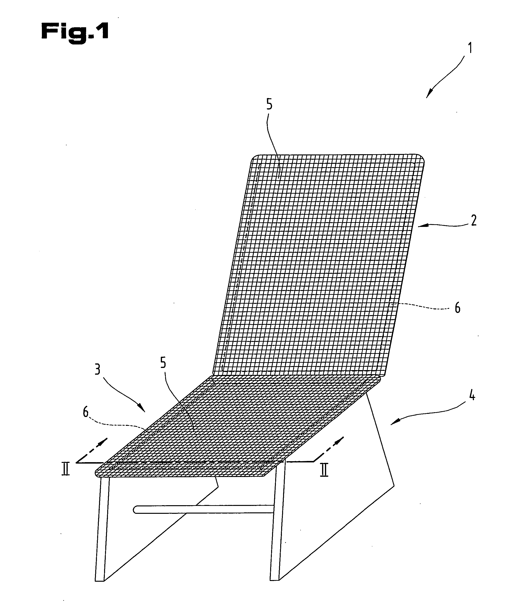
[0058] It should be initially noted that identical components are identified by the same reference symbols or identical component designations in the different embodiments described, wherein characteristics disclosed in the overall description can be transferred analogously to identical components identified by the same reference symbols or the same component designations, respectively. In addition, information on positions such as, e.g., top, bottom, laterally, etc., refers to the respectively described figure and needs to be transferred analogously if the position changes. Furthermore, individual characteristics or combinations of characteristics of the different illustrated and described embodiments may represent independent innovative or inventive solutions.

[0059] All information regarding the value domains in the following description should be understood in such a way that they include any and all subdomains thereof, e.g., the designation 1 to 10 should be understood as inclu...


PUM

PropertyMeasurementUnit
densityaaaaaaaaaa
densityaaaaaaaaaa
densityaaaaaaaaaa

Abstract

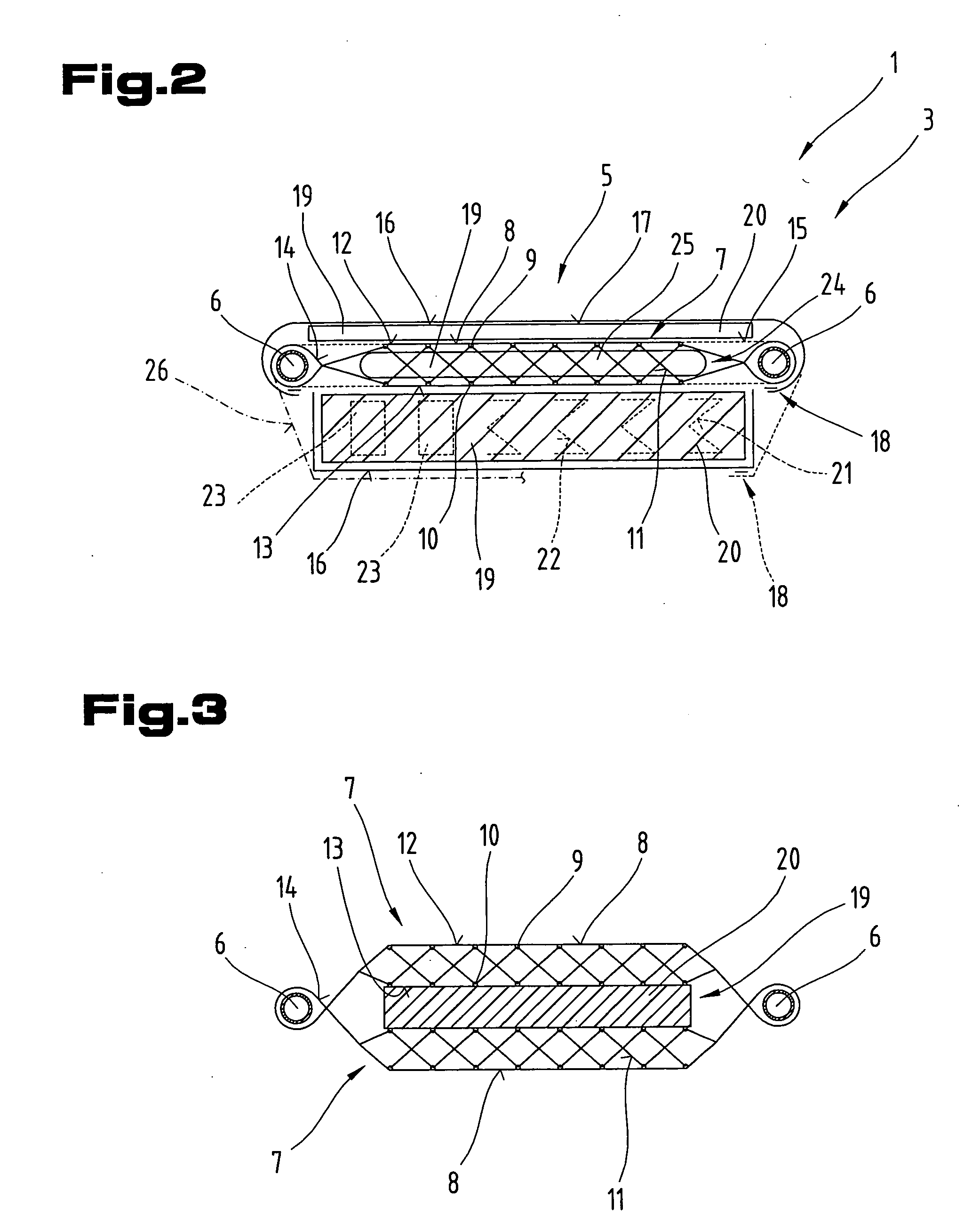
The invention pertains to an upholstery (5) for a passenger seat (1), particularly an aircraft seat, that comprises at least one layer (7, 26) in the form of a textile surface (8) consisting of threads (9 to 11) and / or fibers forming these threads (9 to 11). The textile surface (8) is at least regionally formed by a knitted spacer fabric composed of at least two layers (12, 13) that are spaced apart from one another and pile threads extending therebetween, wherein the textile surface (8) can be at least regionally connected to a supporting frame (6). At least one functional element (19) is at least regionally assigned to the textile surface (8).

Description

BACKGROUND OF THE INVENTION [0001] 1. Field of the Invention [0002] by a knitted spacer fabric composed of at least two layers that are spaced apart from one another and pile threads extending therebetween, and wherein the textile surface can be at least regionally connected to a supporting frame. [0003] 2. The Prior Art [0004] Textile surfaces for furniture such as, for example, chairs, backrests, sitting and reclining surfaces are disclosed in DE 201 18 250 U1 and AT 004 727 U1, respectively. In this case, the textile surface produced with a knitting machines is tentered between at least two frame parts. For reasons of simplicity, the entire textile surface is dimensionally knitted in the required shape. The textile surface furthermore features knitted borders with a narrower mesh width than the surfaces of the textile surface lying therebetween. The knitted borders have the shape of a knitted tube, wherein the tube edges can be pulled over rod-shaped frame elements of the furnitu...

Claims


Application Information

Patent Timeline
Patent Type & Authority Applications(United States)
IPC IPC(8): D04B21/00
CPCA47C5/06A47C31/006B60N2/70B64D11/0647D10B2403/0243D10B2505/08D04B21/20B64D11/0649Y10T442/469Y10T442/40
Inventor MOSENEDER, JOHANN
Owner NEVEON AUSTRIA GMBH
Learn More