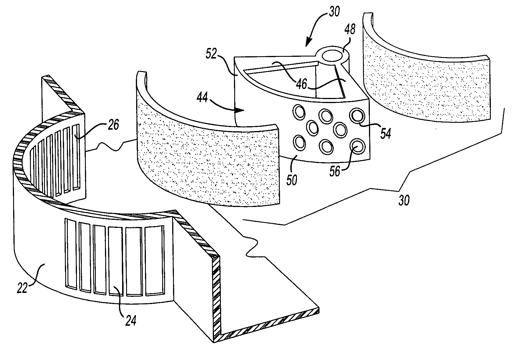
[0019] Referring now to the drawings, FIG. 1 shows a climate control assembly, seen generally at 10, of a type typically used with an automotive vehicle. The climate control assembly 10 includes a housing or case 12 including a heater core 14, an evaporator core 16 and a blower motor 18 driving a blower wheel 20. A blower inlet 22, having a fresh air inlet 24 and a recirculation air inlet 26 is located near the blower wheel 20. The fresh air inlet 24 is typically located such that when the fresh air inlet 24 is open, the climate control assembly 10 draws air from outside the vehicle passenger compartment. The recirculation air inlet 26 is located within the vehicle passenger compartment and when the recirculation air inlet 26 is open, the climate control assembly 10 draws air from inside the vehicle passenger compartment. Accordingly, air, drawn in through either the fresh air inlet 24 or the recirculation air inlet 26, flows in the direction shown by the arrow 28. The blower inlet 22 includes a recirculation door 30 that operates to open and close the respective fresh air inlet 24 and recirculation air inlet 26.
[0020] In operation, air drawn in through either the fresh air inlet 24 or the recirculation air inlet 26, in the direction of the arrow 28, is forced by the blower wheel 20 through the evaporator core 16 and heater core 14 to a distribution plenum 32. From the distribution plenum 32 the air is directed either to the defrost nozzles 34 or heater outlet 36 when the heater core 14 is used to heat the airflow. When the evaporator core 16 operates to cool the airflow, the distribution plenum 32 directs the air through air-conditioning ducts 38 to air-conditioning outlets 40 located in the vehicle dashboard. When operating in the air-conditioning mode, a drain 42 operates to drain condensation and corresponding moisture from the system 10.
[0021] Turning to FIG. 2, there is shown a recirculation door 30 in accordance with the present invention. The recirculation door 30 includes an arcuate door panel 44 configured to fit adjacent the arcuate shaped blower inlet 22. A pair of arm members 46 support the door panel 44 on a bushing 48. The bushing 48 is disposed over a rod or shaft (not shown) whereby the door panel 44 swings back and forth in between first and second positions. In the first position, the door panel 44 closes the recirculation air inlet 26 and opens the fresh air inlet 24. In the second position, the door panel 44 closes the fresh air inlet 24 and opens the recirculation air inlet 26. A suitable drive mechanism operates to move the recirculation door 30 between the first and second positions.
[0022] As illustrated in FIGS. 2-4, the door panel 44 includes an acoustically transparent portion 50 and an acoustically opaque or non-transparent portion 52. As used herein, the term acoustically transparent means allowing the passage of sound waves with minimal reflection. In the preferred embodiment, a portion of the door panel 44 is formed of an acoustically opaque material, such as polypropylene or nylon. Accordingly, the nontransparent or acoustically opaque portion 52 of the door panel 44 is formed of a rigid material that prevents the flow of air and sound waves through the door panel 44. When the acoustically opaque or nontransparent portion 52 of the door panel 44 is placed adjacent the recirculation air inlet 26, it closes the recirculation air inlet to prevent airflow and noise transmission through the recirculation air inlet 26.
[0023] The acoustically transparent portion 50 of the door panel 44 includes a plurality of apertures 54. The apertures allow the sound waves or noise to pass through the acoustically transparent portion 50 of the door panel 44. To prevent airflow through the acoustically transparent portion 50 of the door panel 44, an acoustically transparent member or layer 56 is placed in the apertures 54. As shown herein, the acoustically transparent member or layer 54 is a thermoplastic or polyester member placed in the apertures 56 located in the acoustically transparent portion 50 of the door panel 44. Mylar®, manufactured by DuPont Teijin Films of Hopewell, Va., is one type of thermoplastic or polyester member suitable for use as an acoustically transparent member or layer. It should be understood that the acoustically transparent member or layer 56 operates as an airflow barrier to prevent airflow through the apertures 54 well allowing noise or sound waves to pass through the apertures 54 located in the arcuate door panel 44. Thus, when the acoustically transparent portion 50 of the door panel 44 is placed adjacent the fresh air inlet 24, the acoustically transparent member or layer 56 allows air rush and blower noise, specifically the sound waves generated by operation of the blower and the air moving through the system, to pass through the apertures 54 rather than being reflected back into the vehicle interior through the recirculation inlet 26.
[0024] As illustrated in FIG. 3, the acoustically transparent member or layer 56 is secured within the apertures 54 located in the door panel 44. The apertures 54 includes sloped or beveled sidewalls 58 to redirect sound waves striking the surface of the door panel 44 through the acoustically transparent member 56. Maximizing, the number of apertures 54 located in the door panel 44 increases the overall surface area of the door panel 44 formed of the acoustically transparent member 56. Increasing the surface area formed of the acoustically transparent member 56 correspondingly increases amount of sound or noise that passes through the acoustically transparent portion 50 of the door panel 44.
[0025] Accordingly, since the strength, rigidity and ability to resist airflow forces of the acoustically transparent layer or member 56 varies, the ratio of the acoustically transparent member or layer 56 to the overall area of the acoustically transparent portion 50 of the door panel 44 will vary. Specifically, the acoustically transparent portion 50 of the door panel 44 includes the acoustically transparent member or layer 56 and a portion of the door panel 44 that provides support for the acoustically transparent member or layer 56. The invention contemplates that the acoustically transparent portion 50 of door panel 44 utilized the greatest amount or surface area of acoustically transparent member or layer 56. As set forth above, one approach is a plurality of apertures located in the acoustically transparent portion 50 of the door panel 44. Another approach may include a honeycomb type construction formed of a plurality of thinwall cells, each cell supporting an acoustically transparent member or layer 56 secured and supported within each cell.
[0026] In addition, the door panel 44 may include a seal member 60 placed on one or both sides of the door panel 44. Generally, the seal member 60 is made of a compressible material, such as foam. Suitable foams for use with recirculation doors are known and include for example polyester and polyurethane foams. Such foams also function to reduce any noise reflected back into the housing or case 12 of the climate control assembly 10.
[0027] As illustrated in FIG. 4, the acoustically transparent member or layer 56 is molded within the door panel 44. The sidewalls 58 of the apertures 54 are configured to funnel sound waves through the acoustically transparent member 56. In this embodiment, the acoustically transparent member or layer 56 is a thin film molded into the door panel 44 during the manufacturing process. Once again, the acoustically transparent portion 50 of the door panel 44 supports the acoustically transparent member or layer 56. Accordingly, the acoustically transparent portion 50 of the door panel 44 located adjacent the fresh air inlet 24, when the recirculation door 30 is placed in the recirculation mode, supports the acoustically transparent member or layer 56 adjacent the fresh air inlet 24 thereby allowing passage of noise or sound waves while preventing airflow.
[0028]FIG. 5 illustrates an alternative embodiment of the recirculation door 30 wherein the acoustically transparent member or layer 56 is secured, typically through an adhesive, on one side 62 of the door panel 44 such that the acoustically transparent member or layer 56 covers the apertures 54. As with the previous embodiment, a compressible seal member 60, such as a polyester or polyurethane foam, may be placed over the door panel 44 and correspondingly next to the acoustically transparent member or layer 56. The compressible seal member 60 also provides support for the acoustically transparent member or layer 56 and helps reduce noise transmission within the climate control assembly 10.
[0029]FIG. 6 illustrates the climate control assembly 10 operating in the fresh air mode, where air is drawn in, as illustrated by the arrow 60, through the fresh air inlet 24 for distribution through the housing or case 12 and ultimately through the defroster, 34 heater outlet, 36 or A/C outlets 40. In the fresh air mode, the recirculation door 30 is located at a fresh air position wherein the acoustically opaque or nontransparent portion 52 of the door panel 44 covers the recirculation air inlets 26. Accordingly, as illustrated in FIG. 6, resultant air rush noise along with noise generated from the blower and blower motor noise, illustrated by noise vectors 66, generated in the housing or case 12 strikes the acoustically opaque portion 50 of the door panel 44 and is reflected outward through the fresh air inlet 24.
[0030] Conversely, as illustrated in FIG. 7, placing the recirculation door 30 in the recirculation mode results in air, as illustrated by the arrow 68, being drawn in through the recirculation air inlets 26. When positioned in the recirculation mode, the acoustically transparent portion 50 of the door panel 44 is placed adjacent to and closes the fresh air inlet 24. Accordingly, air rush noise along with blower and blower motor noise, illustrated by noise vectors 70, generated in the housing or case 12 strikes the acoustically transparent portion 50 of the door panel 44 wherein at least a portion of the noise travels through the acoustically transparent portion 50 of the door panel 44 and out the fresh air inlet 24. Accordingly, the acoustically transparent portion 50 of the door panel 44 reduces the noise being reflected back into the vehicle operating compartment through the recirculation air inlet 26.
[0031] While FIGS. 3-6 illustrate one type of acoustically transparent recirculation door 30. Accordingly, the recirculation door 30 of the present invention includes an acoustically transparent portion 50 and an acoustically opaque portion 52. Both portions functioning to reduce the noise level of the climate control assembly 10 by channeling or directing noise generated by the system outwards towards the fresh air inlet 24 and vehicle exterior rather than towards the recirculation air inlet 26 and ultimately the vehicle interior.
[0032] The description of the invention is merely exemplary in nature and, thus, variations that do not depart from the gist of the invention are intended to be within the scope of the invention. Such variations are not to be regarded as a departure from the spirit and scope of the invention.