Telephone apparatus

a telephone and earphone technology, applied in the direction of electrical equipment, substation equipment, interconnection arrangements, etc., can solve the problems of affecting the position deviation between the receiver and the earhole of the user, and the user's voice is difficult to listen to, so as to reduce the overall size of the telephone apparatus, and easily listen to the voice output

Active Publication Date: 2007-05-31
PANASONIC CORP
View PDF6 Cites 10 Cited by
  • Summary
  • Abstract
  • Description
  • Claims
  • Application Information

AI Technical Summary

Benefits of technology

[0014] According to the invention, a speaking source is provided in the vicinity of the upper edge of a telephone apparatus in order to reduce the size of the telephone apparatus. As a result, even when a main tone hole, that is, a first tone hole is blocked by a user's earlobe, a sound from a speaking member can reach the user's earlobe through a sub-tone hole, that is, a second tone hole According to the invention, since at least one of the two tone holes is always opened regardless of the position of the telephone apparatus with respect to a user's ear, it is possible for a user to easily listen to the voice output from the speaking source and thus to listen to a clear voice.
[0015] According to the invention, it is unnecessary to additionally provide a special structure or component in order to provide a sub-tone hole. Therefore, it is possible to reduce the overall size of a telephone apparatus and to prevent an increase in manufacturing costs. Further, it is possible to freely change the position or shape of the sub-tone hole by using the existing constituent component. As a result, there is no restriction in the design of a telephone apparatus, and thus it is possible to design the telephone apparatus to be easily operated.

Problems solved by technology

In the case in which the receiver is arranged closer to the upper end of the main body of the telephone apparatus, when the user holds the main body of the telephone apparatus to a user's ear to listen to a voice, the upper part of the front surface of the main body of the telephone apparatus is put to the entire earlobe of the user, which causes the receiver to be located at a position higher than the earhole, resulting in the positional deviation between the receiver and the earhole of the user.
That is, a tone hole of the main body of the telephone apparatus that transmits a sound output from a speaker for generating a voice deviates from the earhole, which makes it difficult for the user to listen to the voice.
In this case, the user strongly presses the main body of the telephone apparatus against the users ear in order to listen to a clear voice, which causes the tone hole to closely contact with the earlobe, making it more difficult for the user to listen to the voice.

Method used


Image

  • Telephone apparatus
  • Telephone apparatus
  • Telephone apparatus

Examples


first embodiment

[0033] A remote phone of a cordless telephone apparatus, which is an example of a telephone apparatus according to an embodiment of the invention, will be described with reference to the accompanying drawings. In this specification, a receiver held to a user's ear is disposed at the upper side and a transmitter held to a user's mouth is disposed at the lower side, on the basis of the aspect used.

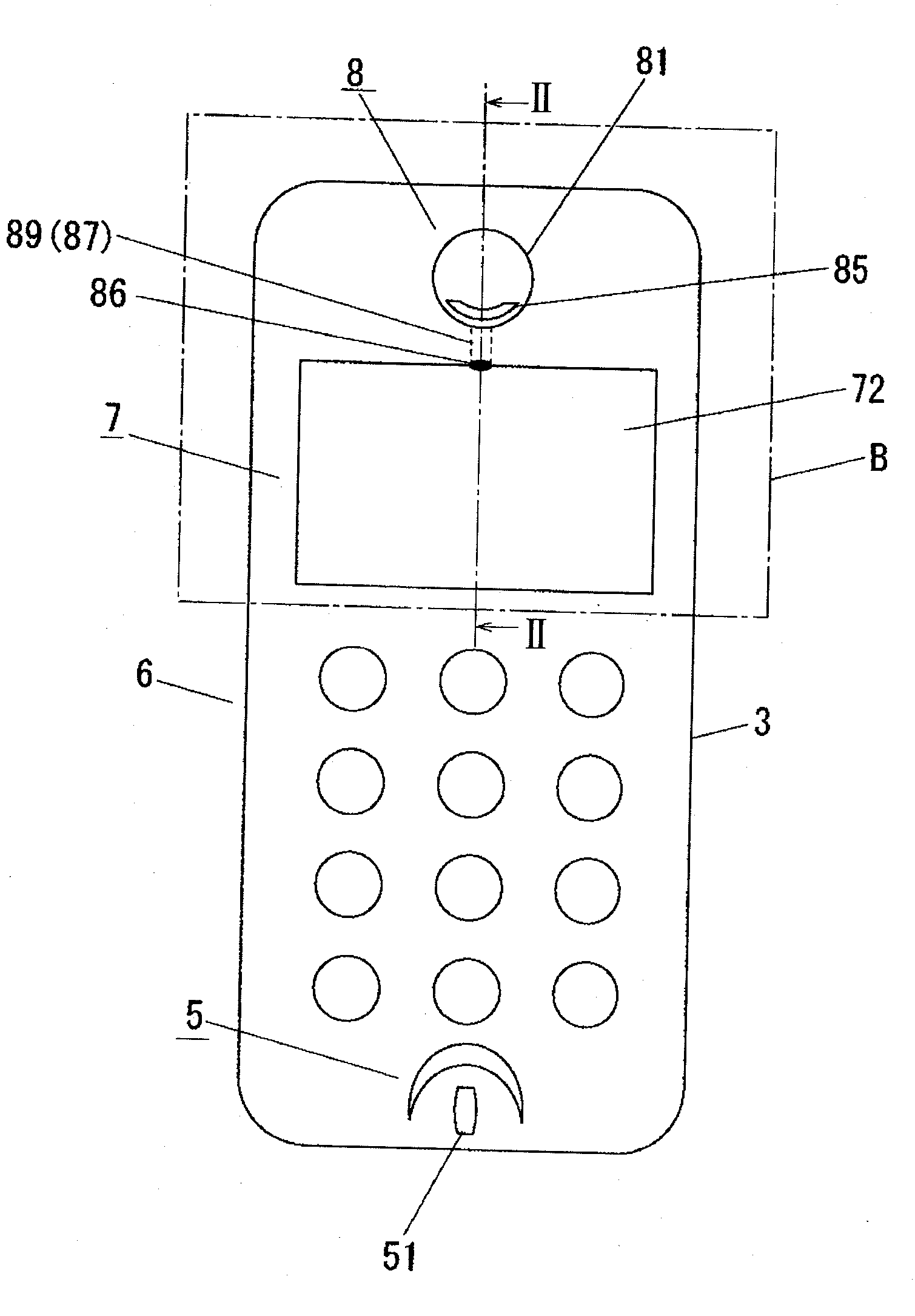
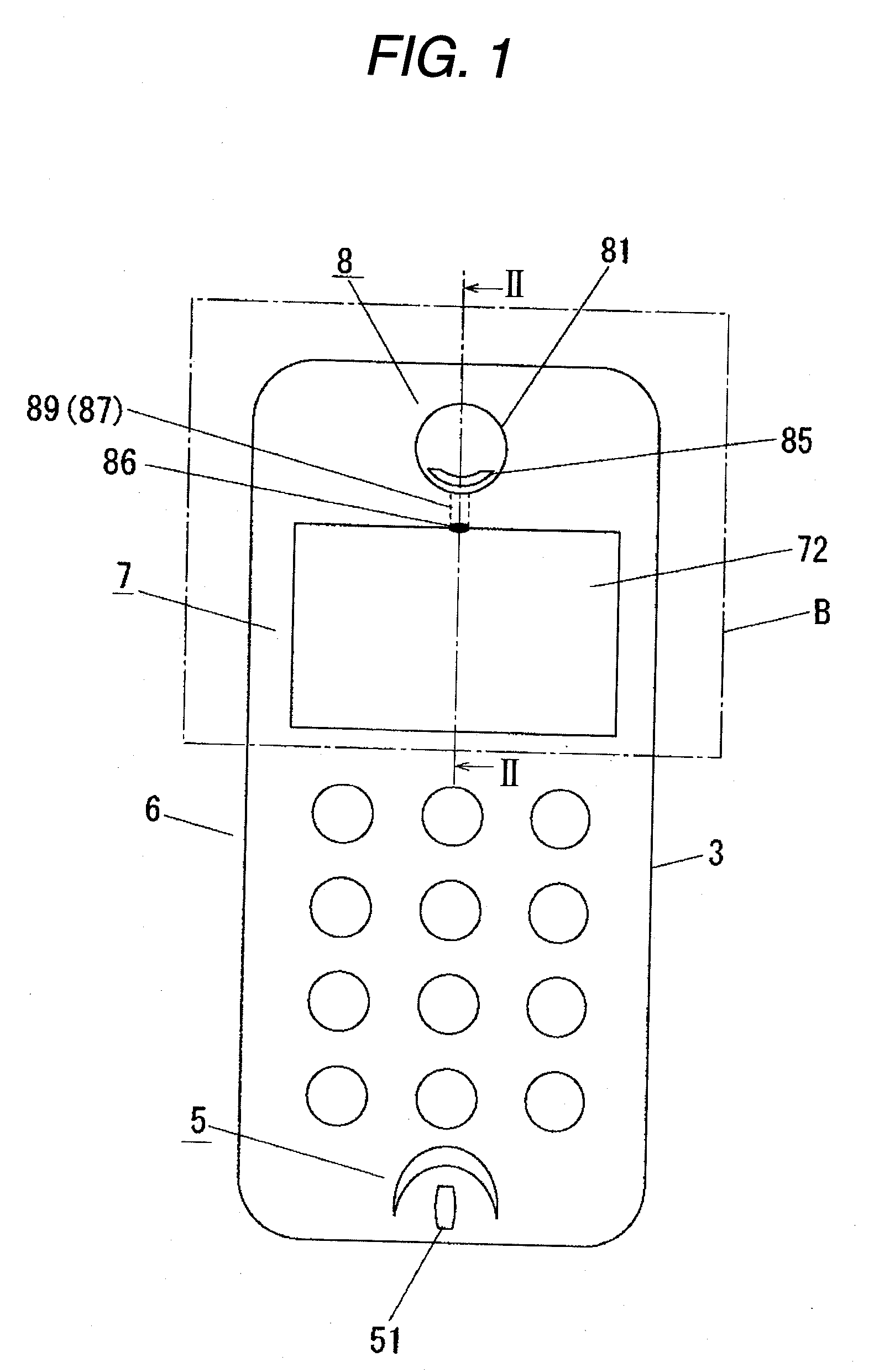
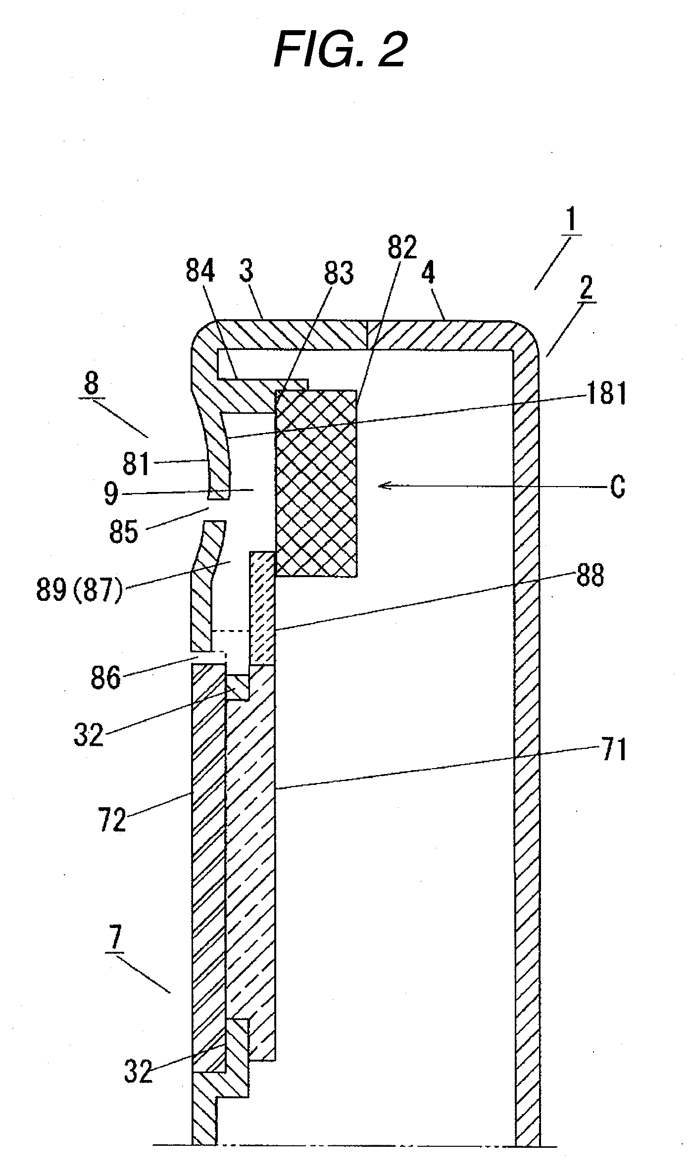
[0034] First, the structure of a telephone apparatus according to a first embodiment will be described with reference to FIGS. 1 to 4. FIG. 1 is a front view of the telephone apparatus according to the first embodiment of the invention. FIG. 2 is a cross-sectional view taken along the line II-II of FIG. 1, FIG. 3 is an enlarged perspective view of a part B of FIG. 1 with a display unit cover detached from a front cover. FIG. 4 is an enlarged perspective view as viewed from a direction C of FIG. 2.

[0035] In FIGS. 1 and 2, the telephone apparatus of this embodiment is driven by a battery (no...

second embodiment

[0060] Next, a remote phone of a cordless telephone apparatus, which is an example of a telephone apparatus according to a second embodiment of the invention, will be described with reference to the accompanying drawings. In particular; in the telephone apparatus according to the second embodiment, a sub-tone hole having another structure from that of the sub-tone hole according to the first embodiment will be described. The second embodiment differs from the first embodiment in that a sub-tone hole is formed in a slit shape in the front surface of a front cover 103. The sub-tone hole in a slit shape has the same width as that of a display unit.

[0061]FIG. 8 is a front view illustrating the telephone apparatus according to the second embodiment of the invention. FIG. 9 is a cross-sectional view taken along the line IX-IX of FIG. 8. FIG. 10 is an enlarged perspective view of a portion E shown in FIG. 8. FIG. 11 is an enlarged perspective view as viewed from a direction of arrow F in ...

third embodiment

[0072] Next, a remote phone of a cordless telephone apparatus, which is an example of a telephone apparatus according to a third embodiment of the invention, will be described with reference to the accompanying drawings. The structure of a propagative chamber of the telephone apparatus according to the third embodiment differs from those according to the first and second embodiment. The third embodiment differs from the first embodiment in that a display unit propagative chamber is provided around a display unit.

[0073]FIGS. 14A and 14B are diagrams illustrating a display unit cover according to the third embodiment of the invention. FIG. 14A is a front view of the display unit cover as viewed from a user, and FIG. 14B is a side view of the display unit cover unit. FIG. 15 is a diagram illustrating the telephone apparatus having the display unit cover shown in FIGS. 14A and 14B attached thereto. FIG. 16 is a cross-sectional view taken along the line XVI-XVI of FIG. 15. In FIGS. 14A ...


PUM


Abstract

Telephone apparatus in that a front cover 3 and a rear cover 4 are combined with each other to form a main body 2, and various components are provided in the main body 2, The front cover 3 includes a transmitter 5, an operating unit 6, a display unit 7, and a receiver 8 from the bottom of the main body 2. In the front cover 3, a main tone hole 85 is provided in the vicinity of a speaker 82, and a sub-tone hole 86 is provided below the speaker 82.

Description

CROSS REFERENCE TO RELATED APPLICATION [0001] This application is based upon and claims the benefit of priority of Japanese Patent Application No. 2005-338220, filed on Nov. 24, 2005, the contents of which are incorporated herein by reference in its entirety. BACKGROUND OF THE INVENTION [0002] 1. Field of the Invention [0003] The present invention relates to a telephone apparatus whose main body is held to a user's ear so that a user listens to a voice output from the telephone apparatus, and more particularly, to the structure of a telephone apparatus enabling a user to listen to a clear voice when the user holds the telephone apparatus to a user's earlobe. [0004] 2. Description of the Related Art [0005] A reduction in the size or weight of telephone apparatuses having good portability, particularly, a remote phone of a cordless telephone apparatus, a cellular phone, and a PHS (personal handy phone system) has made rapid progress. [0006] JP-A-2002-64609 discloses a telephone appara...

Claims


Application Information

Patent Timeline
Patent Type & Authority Applications(United States)
IPC IPC(8): H04M1/00H04M9/00
CPCH04M1/0202H04M1/035
Inventor KONOMI, TOSHIHARUOKADA, YOSHIKAZU
Owner PANASONIC CORP
Why Eureka
Try Eureka