Pulse wave data analyzing method, system, and program product

a data analysis and pulse wave technology, applied in the field of pulse wave data analysis methods, systems and program products, can solve the problems of not easy to automatically detect peaks corresponding to r waves, and the method may misjudge an actual peak as noise, and achieve accurate detection of peaks and bottoms, and high correlation to rr-intervals

Active Publication Date: 2007-05-31
KONICA MINOLTA SENSING INC
View PDF3 Cites 39 Cited by
  • Summary
  • Abstract
  • Description
  • Claims
  • Application Information

AI Technical Summary

Benefits of technology

[0010] In view of the above problems residing in the conventional examples, it is an object of the present invention to provide a pulse wave data analyzing method, a system, and a program product that enable to accurately detect peaks and bottoms by securely removing notch portions included in pulse wave data, even if an arrhythmia or a like symptom has occurred in a subject, and to detect vital information e.g. information having a high correlation to RR-intervals obtained based on an electrocardiogram. Hereinafter, the information is sometimes called as “pulse wave peak-to-peak intervals” in light of obtaining peak-to-peak intervals or bottom-to-bottom intervals.
[0011] An aspect of the invention is directed to a pulse wave data analyzing method for extracting vital information out of pulse wave data concerning a living body. The method comprises a noise removal step of: detecting bottom values and peak values along a time axis in a time-series manner out of pulse

Problems solved by technology

The electrocardiogram measurement using the holter monitor requires the subject to perform a daily activity, with the electrodes being constantly attached to the body, which is stressful to the subject.
It is not easy to automatically detect peaks corresponding to the R waves based on raw pulse wave data according to the

Method used


Image

  • Pulse wave data analyzing method, system, and program product
  • Pulse wave data analyzing method, system, and program product
  • Pulse wave data analyzing method, system, and program product

Examples


Embodiment Construction

[0031] In the following, an embodiment of the invention is described referring to the drawings.

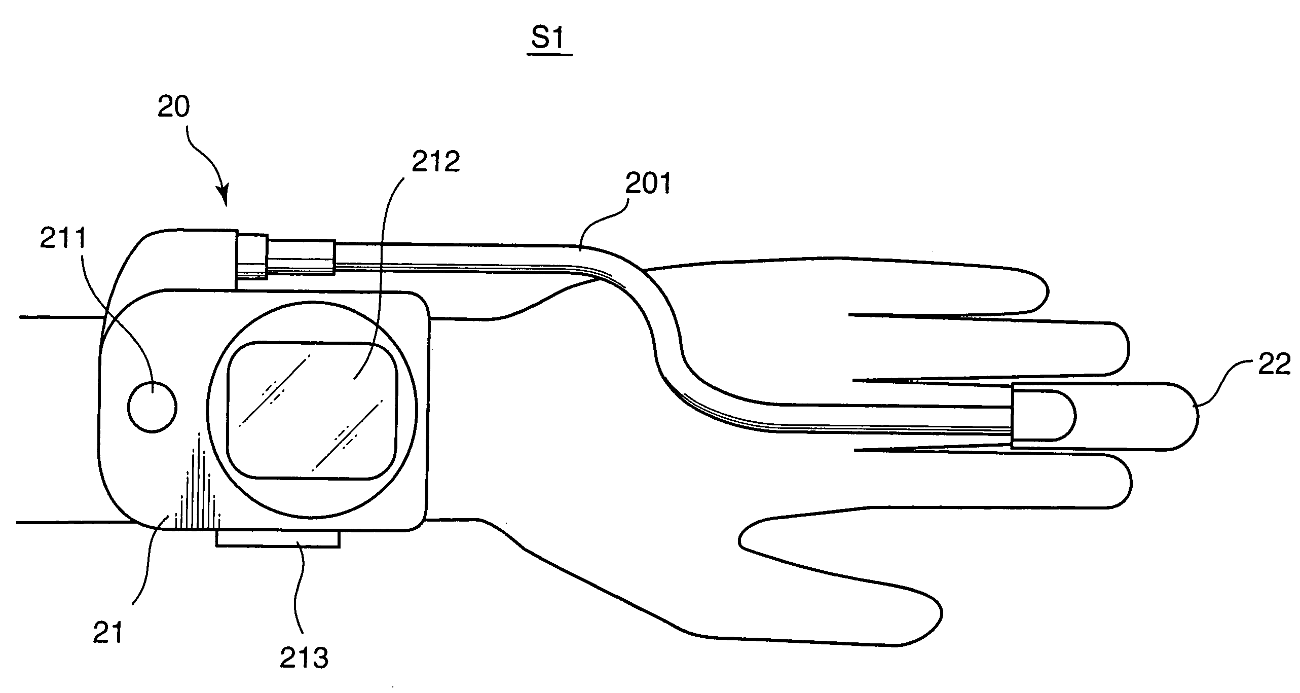
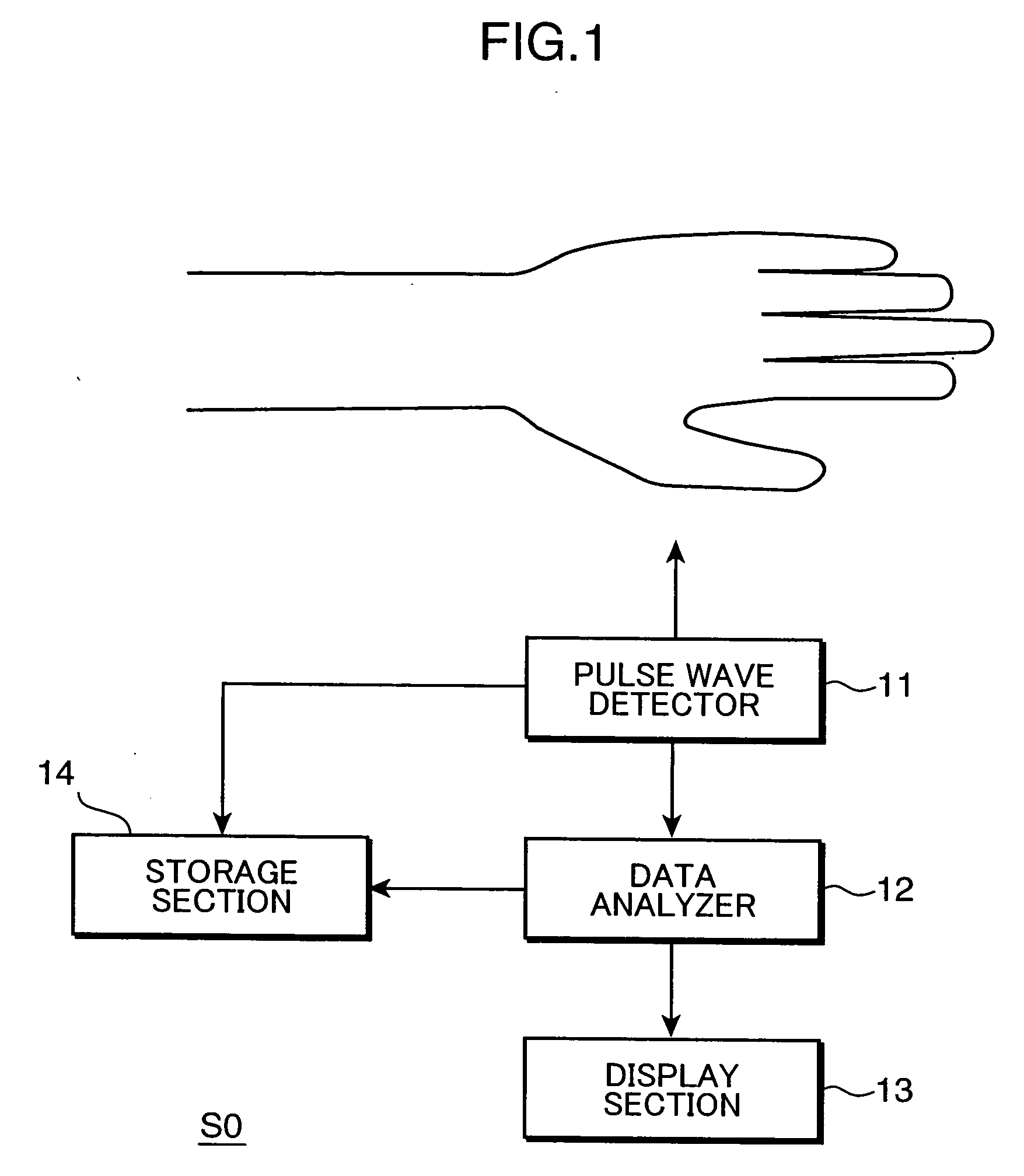
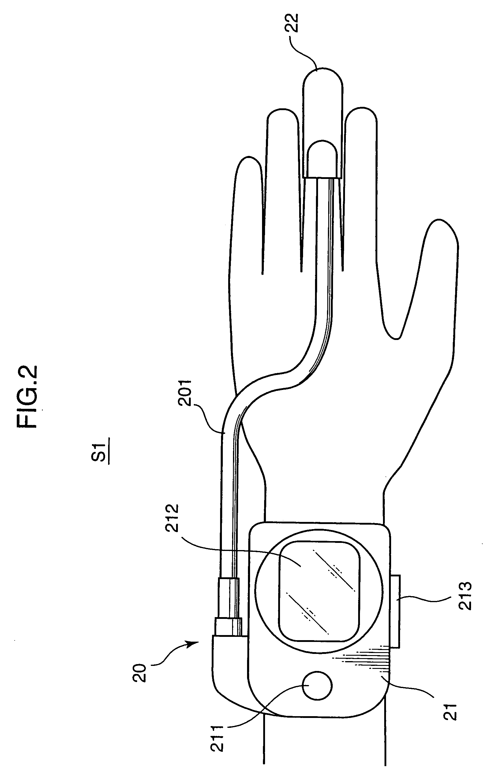
[0032]FIG. 1 is a block diagram schematically showing an entire configuration of a pulse wave data analyzing system “S0” embodying the invention. The pulse wave data analyzing system “S0” is a system capable of extracting information relating to pulse wave peak-to-peak intervals corresponding to RR-intervals in an electrocardiogram, out of pulse wave data concerning a subject i.e. a living body. The pulse wave data analyzing system “S0” includes a pulse wave detector 11, a data analyzer 12, a display section 13, and a storage section 14.

[0033] The pulse wave detector 11 obtains pulse wave information concerning a subject at a predetermined sampling frequency to acquire pulse wave data in association with a time axis i.e. data obtained by sequentially measuring a pulse wave of the subject for a predetermined period. Various pulse wave measuring methods are applicable in the embodiment. A ...


PUM


Abstract

There is provided a pulse wave data analyzing method for extracting vital information out of pulse wave data concerning a living body. The method comprises a noise removal step of: detecting bottom values and peak values along a time axis in a time-series manner out of pulse wave data obtained by sequentially measuring a pulse wave of a subject for a predetermined period; making pairs with respect to the bottom values and the peak values adjacent to each other on the time axis to obtain bottom-to-peak amplitude values along the time axis, the bottom-to-peak amplitude value being a difference between the bottom value and the peak value in each of the pairs; and comparing each set of the two bottom-to-peak amplitude values adjacent to each other along the time axis to remove the bottom value and the peak value relating to the smaller bottom-to-peak amplitude value in the each set as a noise, if a ratio of the one of the two bottom-to-peak amplitude values to the other one of the two bottom-to-peak amplitude values is larger than a predetermined value.

Description

[0001] This application is based on Japanese Patent Application No. 2005-293212 filed on Oct. 6, 2005, and No. 2006-224132 filed on Aug. 21, 2006, respectively, the contents of which are hereby incorporated by reference. BACKGROUND OF THE INVENTION [0002] 1. Field of the Invention [0003] The present invention relates to a pulse wave data analyzing method, a system, and a program product for extracting information corresponding to electrocardiogram RR intervals out of pulse wave data concerning a living body. [0004] 2. Description of the Related Art [0005] There is widely used, as an arrhythmia diagnostic method, a method of measuring an electrocardiogram of a subject, and using RR intervals in the electrocardiogram. The RR interval is a peak-to-peak interval of two consecutive R waves, which are the most frequently observed waves among P waves, Q waves, R waves, S waves, and T waves in one cycle of heartbeat in an electrocardiogram, as shown in FIG. 20. Expressing the RR intervals i...

Claims


Application Information

Patent Timeline
IPC IPC(8): A61B5/04
CPCA61B5/02416A61B5/02438A61B5/0456A61B5/352
Inventor KITAJIMA, KAZUMINAGAI, YOSHIROHFUKUNAMI, MASATAKETSUKAMOTO, YASUMASA
Owner KONICA MINOLTA SENSING INC
Why Eureka
Try Eureka