Distraction instrument and method for distracting an intervertebral site

a technology of intervertebral site and dislocation device, which is applied in the field of dislocation instrument and dislocation device for dislocation of intervertebral site, to achieve the effects of reducing the amount of required impacts, reducing the potential for neural damage, and reducing the impaction of the spin

Inactive Publication Date: 2007-05-31
DEPUY SPINE INC (US)
View PDF76 Cites 220 Cited by
  • Summary
  • Abstract
  • Description
  • Claims
  • Application Information

AI Technical Summary

Benefits of technology

[0014] The present invention provides many advantages, such as desired distraction without the use of distraction linkage or impaction. Further, the present invention utilizes a gear mechanism to control the amount of distraction to a surgical site. Contrary to some distraction instruments described previously, the gear mechanism of the present invention minimizes impaction of the spine. The use of the gear mechanism of the present invention decreases the amount of required impacts during the procedure, thereby significantly reducing the potential for neural damage.

Problems solved by technology

Actuation of the gear mechanism causes the head to move the distraction instrument from a reduced position to a distraction position, thereby causing distraction of vertebrae at an intervertebral site into which a portion of the arms distal to the housing have been inserted.

Method used


Image

  • Distraction instrument and method for distracting an intervertebral site
  • Distraction instrument and method for distracting an intervertebral site
  • Distraction instrument and method for distracting an intervertebral site

Examples


first embodiment

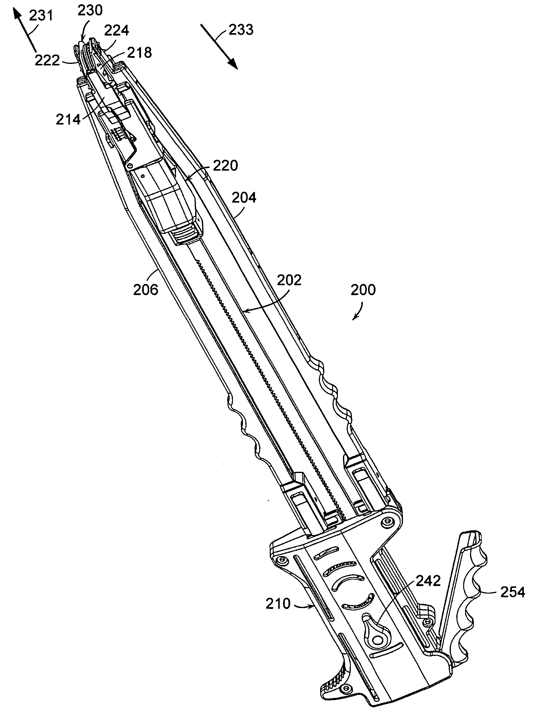
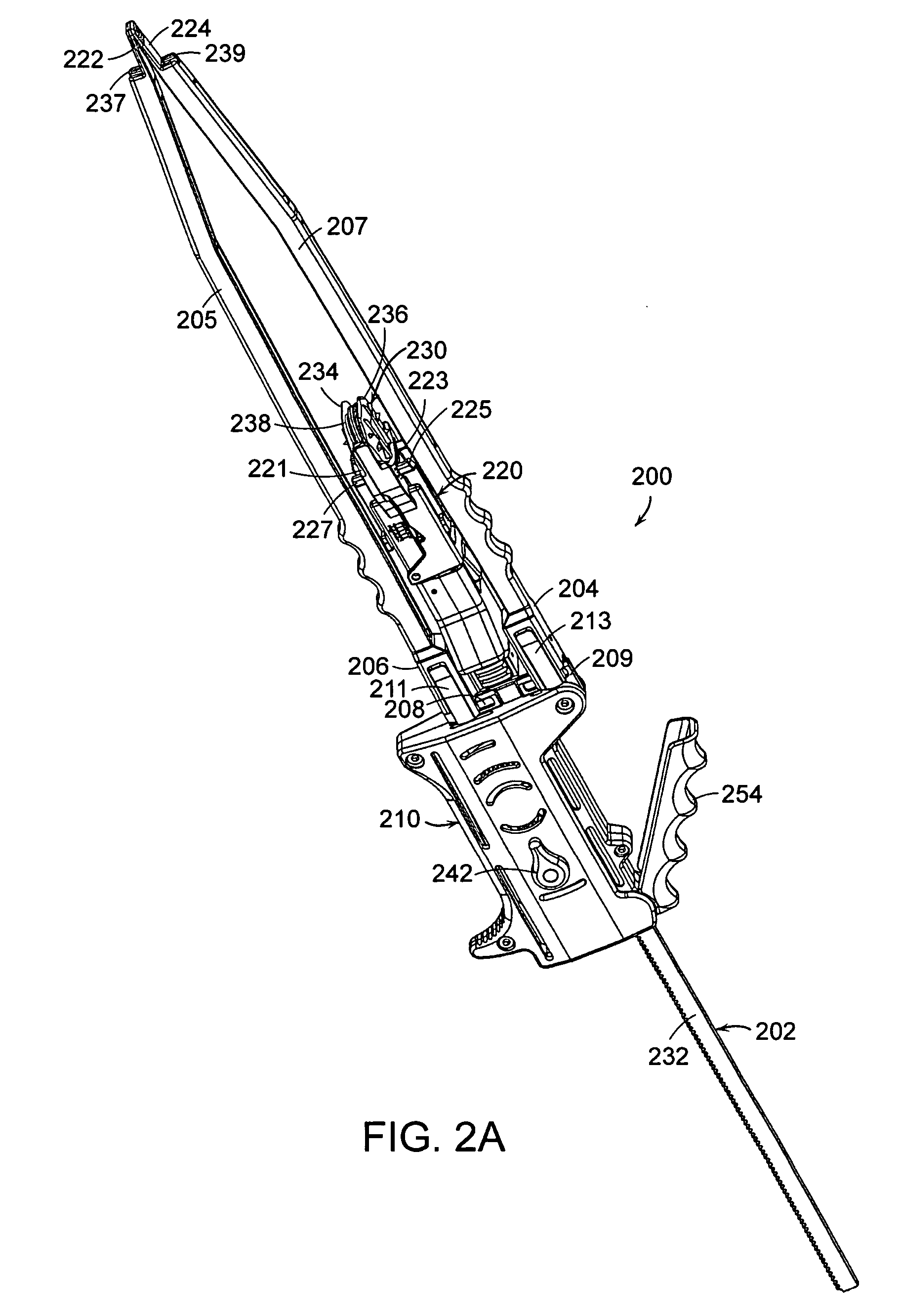
[0048] In the distraction instrument of the present invention, shown in FIGS. 2A and 2B, distraction instrument 200 includes drive rod 202, distraction arms 204, 206 and driver mechanism 210. Driver mechanism 210 operates by a gear mechanism, meaning that the incremental actuating movements of the gears propel drive rod 202 towards or away from intervertebral site 150′ (FIG. 1). In turn, drive rod 202 moves linearly along an axis.

[0049]FIG. 2A shows distraction instrument 200 in a reduced position. FIG. 2B shows distraction instrument 200 in a distracted position. In both FIGS. 2A and 2B, drive rod 202 is coupled to implant holder 220, which holds artificial disc 230. Located between arms 204, 206 is drive rod 202. Implant holder 220 is a work piece that is put in motion to transport artificial disc 230 into intervertebral site 150′ (FIG. 1). Implant holder 220 is releasably coupled to both artificial disc 230 and drive rod 202, wherein artificial disc 230 is located at a distal end...

second embodiment

[0053] In a second embodiment, ratcheting gear mechanism 243, shown in FIGS. 4A and 4B, includes three wheel gears and two diametrically opposed straight gears 267, 268. The three wheel gears consist of two outer wheel gears 262, 266 and inner wheel gear 264. Each of the outer wheel gears are paired with one of the two straight gears, and only one outer wheel gear-straight gear pair is actuated depending on the mode of driver mechanism 210.

[0054] The mode of the ratcheting gear mechanism is controlled by switch 242. In one embodiment, shown in FIGS. 3C and 3D, there are two modes of operation: a driving mode and a free-floating mode. In another embodiment, shown in FIGS. 4A through 4D, the gear mechanism can have three modes of operation: a driving, a removal and a free-floating mode. When switch 242 is set in a driving mode or position, shown in FIGS. 4A and 4B, actuation of lever 254 engages straight gear 267 with outer wheel gear 266, whereby inner wheel gear 264 linearly moves d...


PUM


Abstract

A distraction instrument includes a drive rod, a driver mechanism coupled to the drive rod, and a pair of arms linked to the driver mechanism. A method of implanting an artificial disc or a fusion implant in an intervertebral site includes preparing the intervertebral site, actuating a gear mechanism of a distraction instrument to distract the intervertebral site, and inserting at least a core of the artificial disc or fusion implant into the intervertebral site.

Description

BACKGROUND OF THE INVENTION [0001] Spinal surgery involves many challenges as the long-term health and mobility of the patient often depends on the surgeon's technique and precision. One type of spinal surgery involves the removal of the natural disc tissue that is located between adjacent vertebral bodies. Procedures are known in which the natural, damaged disc tissue is replaced with an interbody cage or fusion device, or with a disc prosthesis. [0002] The insertion of an article, such as an artificial disc prosthesis, presents the surgeon with several challenges. The adjacent vertebral bodies collapse upon each other once the natural disc tissue is removed. These bodies must be separated to an extent sufficient to enable the placement of the prosthesis. However, if the vertebral bodies are separated, or distracted, to beyond a certain degree, further injury can occur. The disc prosthesis must also be properly positioned between the adjacent vertebral bodies. Malpositioning of the...

Claims


Application Information

Patent Timeline
Patent Type & Authority Applications(United States)
IPC IPC(8): A61F2/00
CPCA61F2/4611A61F2002/4627A61F2002/4628
Inventor STAD, SHAWN D.FATYOL, PATRICKGRACIA, MARK
Owner DEPUY SPINE INC (US)
Why Eureka
Try Eureka