Method and device for multi phase error-correction
a multi-phase error correction and error correction technology, applied in the field of multi-phase error correction, can solve problems such as unintentional introduction of errors, increase of code length, complexity and area of encoder and decoder circuitry,
- Summary
- Abstract
- Description
- Claims
- Application Information
AI Technical Summary
Benefits of technology
Problems solved by technology
Method used
Image
Examples
example case 1
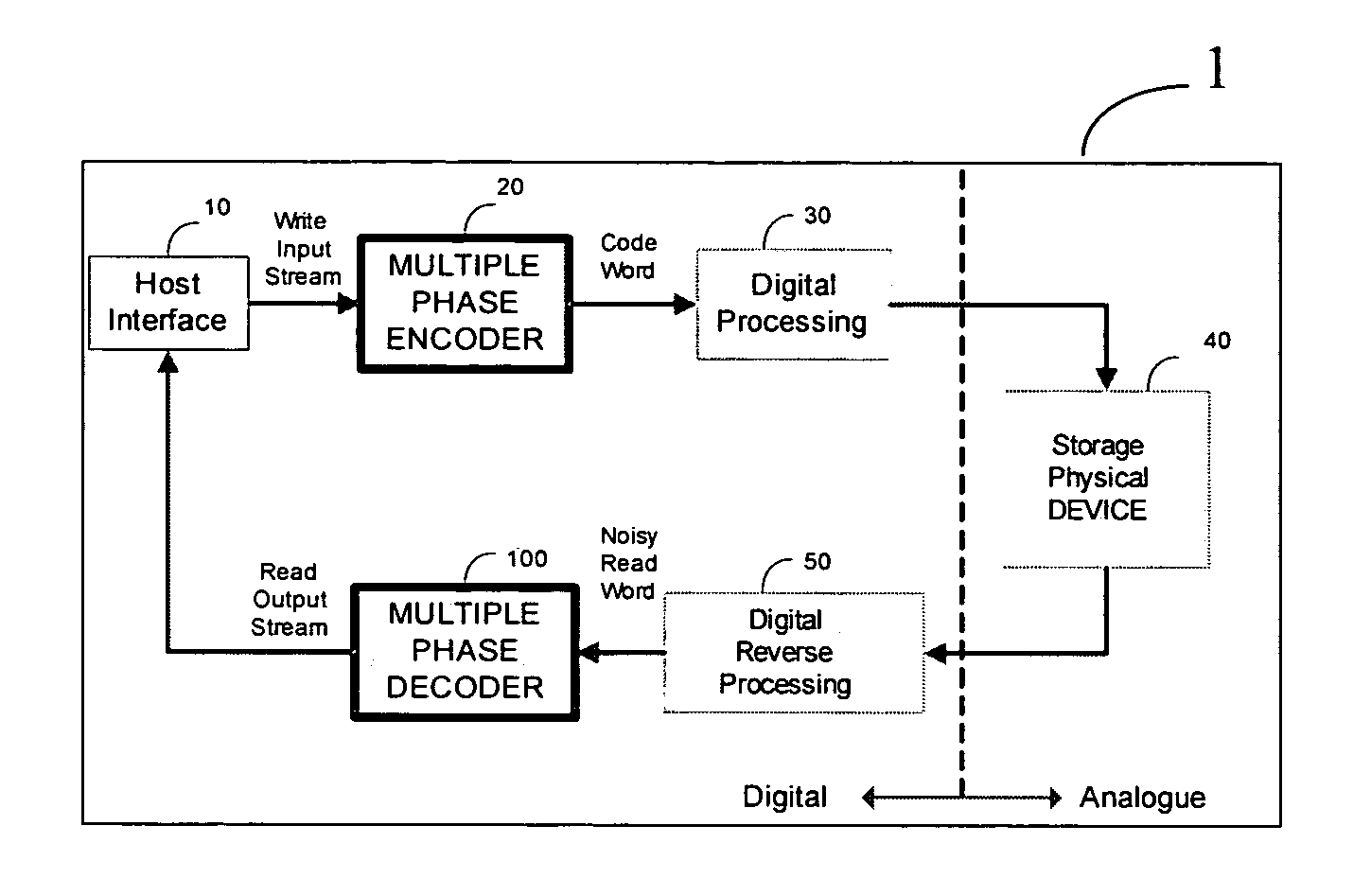
[0107] There is provided a FLASH device containing independent bits, wherein there is one bit per nucleus cell and the Cell Error Rate (CER) is 4.7×10⁻⁵. Because the FLASH device has one bit per cell, the Bit Error Rate (BER) is also 4.7×10⁻⁵. A flash memory of the FLASH device includes many blocks; each block defined having several pages. Each page includes a header or control area and several sectors each of which is 512 data bytes long. It is required to design an error correction coding scheme in the flash controller for the FLASH device, while providing reliable storage for the header of each block containing 14 bits and achieving a Header Error Rate (HER) performance lower than 10−10 (HER−10).
[0108] A 3 bit error correction capability is required for providing the performance goal of HER−10 over a set of 14 bits with an input CER of 4.7×10⁻⁵. The correction of one error (i.e. t=1) provides HER˜3.8×10⁻⁷ and the correction of two errors (i.e. t=2) provides HER˜2.1×10⁻¹⁰.
[0109]...
example case-1
MATHEMATICAL ANALYSIS OF EXAMPLE CASE-1
[0151] The following section describes in detail the mathematical analysis performed in the method of the present invention in order to evaluate the achieved gain in size and circuitry complexity. The achieved gain related to controller complexity is obvious, since the implementation of a decoder that is capable of correcting two errors is simpler than the implementation of a decoder that is capable of correcting 3 errors.
[0152] For computing the reference scheme, let p be defined as the FLASH device input BER (i.e. in our example p=4.7×10⁻⁵). The HER performance of the decoder, wherein [n=15,k=7,d=5,t=2], is given according to the binomial distribution as follows: HERt=2,n=15=∑i=323(24ⅈ)·pⅈ·(1-p)24-ⅈ|p=4.7·10-5=2.1×10⁻¹⁰,(1.4)
wherein ‘t’ refers to the error correction capability (i.e. the maximum number of erroneous bits that can be corrected) as follows: t=└(d−1) / 2┘. Because according to (1.4) it is insufficient to correct two errors, ...
example case 2
[0160] There is provided the same FLASH device as disclosed above in Example case 1, i.e. there is one bit per cell and the Cell Error Rate (CER) is 4.7×10⁻⁵. It is required to design a FLASH device comprising a decoder, such that the decoder is implemented to provide reliable storage of a sector data area containing 512 bytes (of 8 bits each). Since the data itself is of less importance than the header of each sector, then the target performance for the data, i.e. SER (Sector Error Rate), is lower than 5×10⁻⁸. The design of the FLASH device is limited to a simple ECC (Error Correction Code) hardware (i.e. a 15 bit block code, as already designed for the header).
[0161] The correction of t=1 error obtains SER˜1.36×10⁻⁴. The correction of t=2 errors obtains SER˜2.8×10⁻⁸. The code rate R is defined by the number of information bits k divided by the code length n. In other words, using a total of ┌512×8 / 7┐=586 code words to represent the sector of length 4096 bits provides a total code...
PUM
 Abstract
Description
Claims
Application Information
 - R&D
- Intellectual Property
- Life Sciences
- Materials
- Tech Scout
- Unparalleled Data Quality
- Higher Quality Content
- 60% Fewer Hallucinations
Browse by: Latest US Patents, China's latest patents, Technical Efficacy Thesaurus, Application Domain, Technology Topic, Popular Technical Reports.
© 2025 PatSnap. All rights reserved.Legal|Privacy policy|Modern Slavery Act Transparency Statement|Sitemap|About US| Contact US: help@patsnap.com


