Control method for spinning cycle in washing machine

a control method and washing machine technology, applied in other washing machines, domestic applications, textiles and papermaking, etc., can solve problems such as unbalance of laundry, vibration or unbalance of a body, and bad influence on the rigidity of the system, so as to enhance drainage and dehydration ability, and minimize the effect of over-vibration

Inactive Publication Date: 2007-06-07
LG ELECTRONICS INC
View PDF4 Cites 65 Cited by
  • Summary
  • Abstract
  • Description
  • Claims
  • Application Information

AI Technical Summary

Benefits of technology

[0020] An object of the present invention is to provide a control method for a spinning cycle in a washing machine which can minimize over-vibration generated in a spinning cycle and can enhance drainage and dehydration capability.

Problems solved by technology

If the laundry is not uniformly distributed during the spinning cycle, there might be unbalance of the laundry.
Thus, it is needed to sense the RPM of the motor in a beginning of a spinning cycle, such that vibration or unbalance of a body may be sensed by variation of RPM.
That is, in case the drum is rotated in more than the allowable range of laundry unbalance in the beginning of the spinning cycle, there may be bad influence on entire rigidity of the system.
However, a spinning cycle according to the related art senses laundry unbalance only once when accelerating the motor before starting a high speed spinning, thereby resulting in mal-sensing of laundry unbalance.
Especially, in case that laundry unbalance is mal-sensed in a spinning cycle at 200˜300 RPM in that resonance is generated, severe vibration is generated enough to cause damage such as glass scratch of a door or washing machine moving.
Also, since water leaked from the laundry by centrifugal force may be stuck to a wall of the drum after a predetermined RPM of high speed spinning according to the related art, normal drainage may not be performed.
Thus, the remaining water within the drum may be a cause of severe vibration or noise in a high speed spinning, thereby resulting in customer dissatisfaction.

Method used


Image

  • Control method for spinning cycle in washing machine
  • Control method for spinning cycle in washing machine
  • Control method for spinning cycle in washing machine

Examples


Embodiment Construction

[0039] Reference will now be made in detail to the preferred embodiments of the present invention, examples of which are illustrated in the accompanying drawings. Wherever possible, the same reference numbers will be used throughout the drawings to refer to the same or like parts.

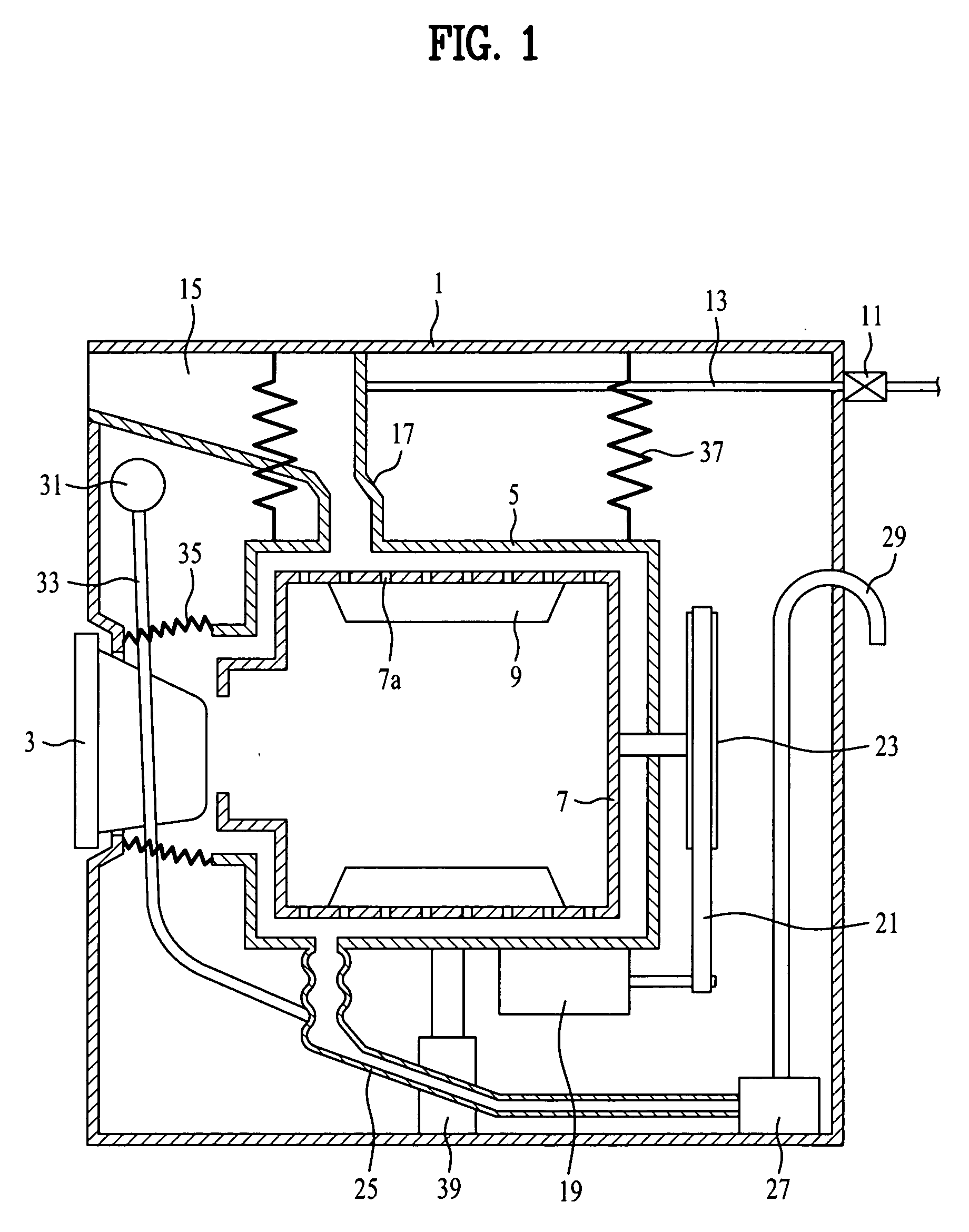
[0040] Referring to FIG. 1, a conventional drum type washing machine to which a spinning algorithm of the present invention may be applied.

[0041] The conventional drum type washing machine includes an outer case 1 for defining an exterior thereof, a door 3 rotatably coupled to a front surface of the outer case 1 to load / unload the laundry smoothly.

[0042] A tub 5 is mounted within the outer case 1 to hold wash water performing washing. A drum 7 is rotatably mounted within the tub 5 and has plural spinning holes 7a formed on a surface thereof to drain water of the laundry when the drum is rotated at a high speed.

[0043] A lifter 9 is mounted in a side of a drum inside to lift the laundry to a predetermined...


PUM


Abstract

A control method for a spinning cycle in a washing machine is disclosed. The control method for a spinning cycle in a washing machine includes (a) step of performing a water-draining by rotating a motor at a predetermined speed lower than a resonance generation speed and (b) step of performing a main-spinning by rotating the motor at a speed higher than the resonance generation speed. The control method for a spinning cycle in a washing machine according to the present invention has an advantageous effect that over-vibration caused by unbalance may be controlled and that remaining water within the drum is drained smoothly and vibration/noise of a washing machine is minimized.

Description

[0001] This application claims the benefit of the Patent Korean Application Nos. P2005-70172 and No. P2005-70174, filed on Aug. 1, 2005, which are hereby incorporated by reference as if fully set forth herein. BACKGROUND OF THE INVENTION [0002] 1. Field of the Invention [0003] The present invention relates to a washing machine, more particularly, to a control method a spinning cycle in a washing machine which can minimize over-vibration generated in a spinning cycle and can enhance drainage and dehydration capability. [0004] 2. Discussion of the Related Art [0005] In general, a washing machine is an electric appliance used most commonly in a house. The washing machine washes cloth items, clothes and beddings (hereinafter, the laundry) by using friction poser of wash water current generated by rotation movement and shock power with the laundry, in a state where wash water, detergent and the laundry are mixedly loaded into a drum. [0006] The washing machine is classified into a pulsto...

Claims


Application Information

Patent Timeline
Patent Type & Authority Applications(United States)
IPC IPC(8): D06F35/00D06F39/00D06F33/40D06F33/48
CPCD06F35/007D06F37/203D06F33/48D06F33/40D06F2103/26D06F2105/52
Inventor KWON, IG GEUNKANG, DONG WON
Owner LG ELECTRONICS INC
Why Eureka
Try Eureka