Methods and apparatus for assembling gas turbine engines

a gas turbine engine and gas turbine technology, applied in the direction of machines/engines, vessel construction, marine propulsion, etc., can solve the problems of premature fatigue of support struts, high temperature airflow, and large thermal gradient, and achieve the effect of facilitating the direction of a portion

Active Publication Date: 2007-06-07
GENERAL ELECTRIC CO
View PDF7 Cites 10 Cited by
  • Summary
  • Abstract
  • Description
  • Claims
  • Application Information

AI Technical Summary

Benefits of technology

[0007] In another aspect, a nozzle assembly is provided for an engine including a core engine and at least one bypass duct for channeling airflow around the core engine. The nozzle assembly includes a liner comprising an inner surface and an outer surface, wherein the inner surface confines airflow within a nozzle bypass duct, and the outer surface confines airflow discharged from the core engine. A plurality of strut members are coupled to and support the liner. A plurality of fairings are in flow communication with the at least one bypass duct, and each fairing is upstream from a respective one of the plurality of strut members to facilitate directing a portion of the airflow from the bypass duct past the plurality of strut members.

Problems solved by technology

As such, because these support struts are positioned within the flow path of the exhausted core engine airflow, the support struts are exposed to high temperature airflows and may be subjected to large thermal gradients generated from the hot core engine airflow and the cool bypass airflow.
Over time, the support struts may be prematurely fatigued of damaged due to continued exposure to high operating temperatures generated by the gas turbine engine.

Method used


Image

  • Methods and apparatus for assembling gas turbine engines
  • Methods and apparatus for assembling gas turbine engines
  • Methods and apparatus for assembling gas turbine engines

Examples


Embodiment Construction

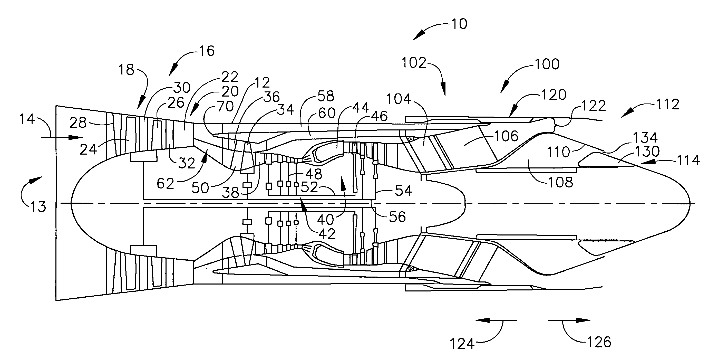
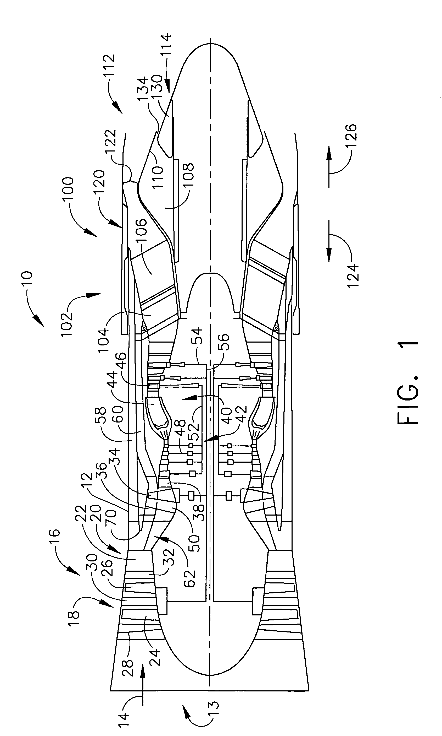
[0012]FIG. 1 is a cross-sectional view of a portion of an exemplary gas turbine engine 10 that includes an outer casing 12 having an upstream end 13 that forms an inlet 14 sized to provide a predetermined quantity of airflow to the engine 10. Disposed within inlet 14 is a fan 16 for receiving and compressing airflow channeled through inlet 14. Fan16 includes a forward section 18 that is axially displaced from an aft section 20 by an axial space 22. In the exemplary embodiment, forward section 18 includes a pair of rows of rotor blades 24 and 26 that are interspaced between rows of inlet guide vanes 28 and stator vanes 30 and 32. Similarly, aft fan section 20 includes at least one stage of rotor blades 34 that are interspaced between adjacent rows of aft fan stator vanes 36 and 38.

[0013] Gas turbine engine 10 also includes a core engine 40 that is downstream of fan 16. In the exemplary embodiment, core engine 40 includes an axial flow compressor 42 upstream of a combustor 44 and a h...


PUM


Abstract

A method is provided for operating a gas turbine engine including a core engine having a core stream duct, an inner bypass duct, an outer bypass duct, and a nozzle assembly downstream of the core engine and including a core engine nozzle and a bypass nozzle separated by a liner. The method includes channeling a first airflow discharged from the core gas turbine engine to the core engine nozzle, and channeling a second airflow through the inner bypass duct such that the second airflow bypasses the core gas turbine engine. The second airflow is channeled to a plurality of fairings that are positioned upstream from a plurality of support struts coupled to the nozzle assembly liner. The method also includes channeling a third airflow through the outer bypass duct such that the third airflow bypasses the core gas turbine engine, wherein the third airflow is channeled through the support struts to the bypass nozzle.

Description

[0001] The U.S. Government may have certain rights in this invention pursuant to contract number MDA972-01-3-0002.BACKGROUND OF THE INVENTION [0002] The present invention relates to gas turbine engines and more particularly, to methods and apparatus to facilitate controlling gas turbine engine bypass airflows. [0003] At least one known gas turbine engine includes, in serial flow arrangement, a forward fan assembly, an aft fan assembly, a high-pressure compressor for compressing air flowing through the engine, a combustor for mixing fuel with the compressed air such that the mixture may be ignited, and a high pressure turbine. The high-pressure compressor, combustor and high-pressure turbine are sometimes collectively referred to as the core engine. In operation, the core engine generates combustion gases which are discharged downstream to a low pressure turbine that extracts energy therefrom for powering the forward and aft fan assemblies. [0004] In addition to flow considerations, ...

Claims


Application Information

Patent Timeline
Patent Type & Authority Applications(United States)
IPC IPC(8): F02K3/02
CPCF02K1/04F02K1/78F02K3/04F02K3/075F02K3/077
Inventor RENGGLI, BERNARD JAMESJUMPER, MATTHEW WILSON
Owner GENERAL ELECTRIC CO
Why Eureka
Try Eureka