Printhead cartridge with bracing for reducing structural deflection

a technology of structural deflection and printhead, which is applied in the direction of printing, other printing apparatus, etc., can solve the problems of unattainable speed with conventional inkjet printers, inability to replace these parts, and printers employing reciprocating type printheads. achieve the effect of facilitating the replacement of printhead cartridges and accurate and secure positioning of cartridges

Inactive Publication Date: 2007-06-07
SILVERBROOK RES PTY LTD
View PDF13 Cites 23 Cited by
  • Summary
  • Abstract
  • Description
  • Claims
  • Application Information

AI Technical Summary

Benefits of technology

[0003] This invention relates to a printer having a replaceable printhead cartridge. It has been developed primarily for facilitating replacement of the printhead cartridge by a user, whilst ensuring accurate and secure positioning of the cartridge.

Problems solved by technology

Replacement of these parts is not possible without replacement of the entire printer.
As well as being rather fixed in their design construction, printers employing reciprocating type printheads are relatively slow, particularly when performing print jobs of full colour and / or photo quality.
Such speeds were unattainable with conventional inkjet printers.
Unfortunately, individual nozzles on a printhead will malfunction through clogging, air bubbles in the ink, fabrication errors and so on.
Obviously, this is detrimental to print quality.
It is possible to combat this with dead nozzle compensation in the print engine controller (PEC) and nozzle redundancy (surplus nozzles) on the printhead, However, eventually too many nozzles will fail for these mechanisms to work, and the print quality is compromised.
This has disadvantages for both the end user and the manufacturer.
One particular complication with a replaceable pagewidth printhead involves the number of power and data contacts that need to connect to the printers onboard PEC.
This is inconvenient for users and puts a large and potentially damaging load on the structure of the printhead and the printer.
However, simply increasing the size and overall robustness of the cartridge structure comes at a manufacturing and materials cost.

Method used


Image

  • Printhead cartridge with bracing for reducing structural deflection
  • Printhead cartridge with bracing for reducing structural deflection
  • Printhead cartridge with bracing for reducing structural deflection

Examples


Embodiment Construction

Printer Casing

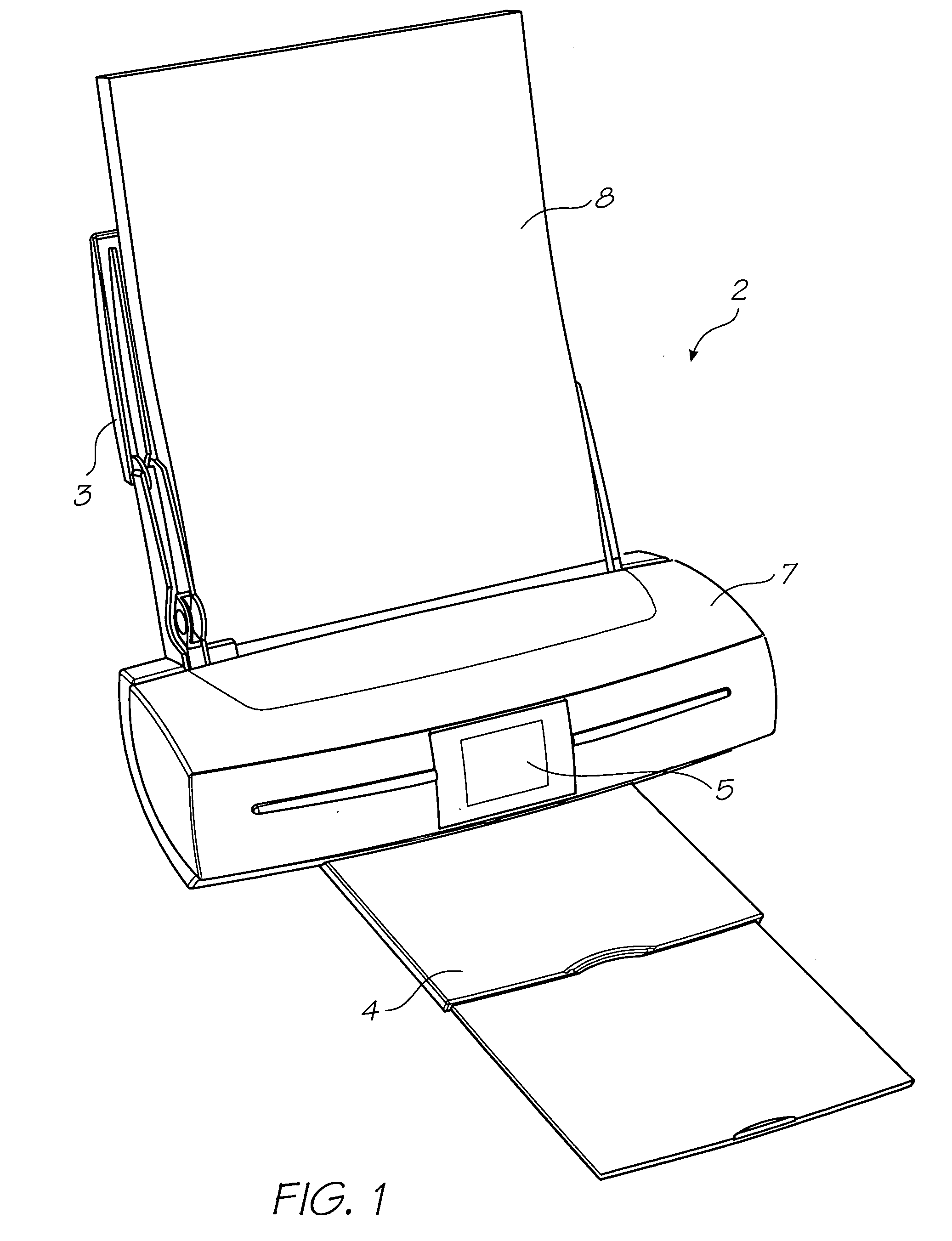
[0398]FIG. 1 shows a printer 2 embodying the present invention. Media supply tray 3 supports and supplies media 8 to be printed by the print engine (concealed within the printer casing). Printed sheets of media 8 are fed from the print engine to a media output tray 4 for collection. User interface 5 is an LCD touch screen and enables a user to control the operation of the printer 2.

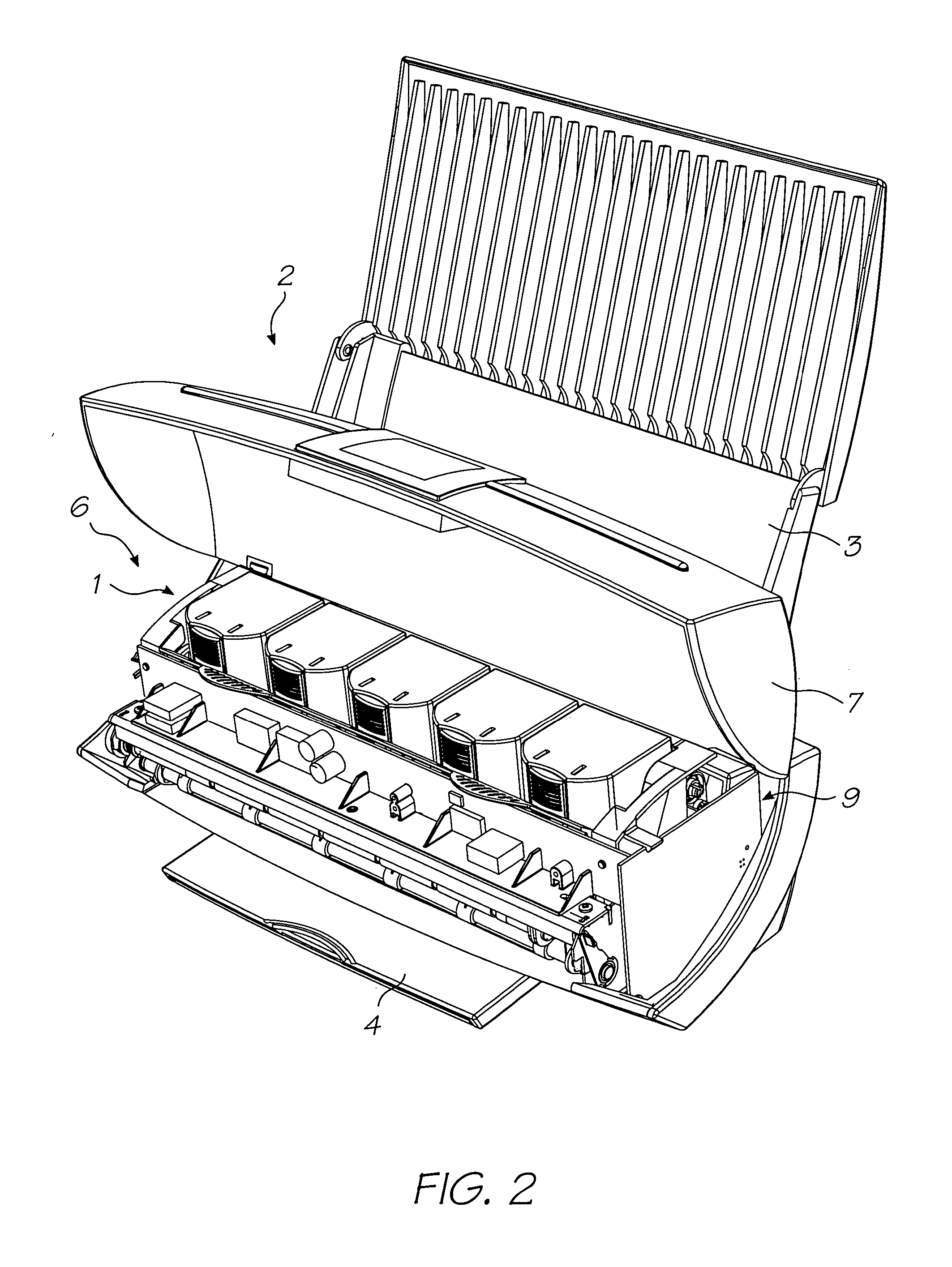
[0399]FIG. 2 shows the lid 7 of the printer 2 open to expose the print engine 1 positioned in the internal cavity 6. Picker mechanism 9 engages the media in the input tray 3 (not shown for clarity) and feeds individual streets to the print engine 1. The print engine 1 includes media transport means that takes the individual sheets and feeds them past a printhead (described below) for printing and subsequent delivery to the media output tray 4 (shown retracted). The printer 2 shown has an L-shaped paper path which is convenient for desktop printers. However, described below is a printer cr...


PUM


Abstract

An inkjet printer comprising: a printer body and a replaceable printhead cartridge, the printhead cartridge having a casing that supports a pagewidth printhead; the printer body having a cradle for holding the printhead cartridge in an operative position such that the pagewidth printhead is adjacent a paper path defined by the printer body, the cradle having a fulcrum formation for engaging a complementary formation on the casing upon insertion of the cartridge so that it rotates into the operative position; wherein, the cradle has a biased locating abutment to apply a compressive force that maintains the printhead cartridge in the operative position and the casing has a structural member extending from the complementary formation; such that during use, the structural member extends from the locating abutment to the complementary formation and is aligned with the direction of the compressive force.

Description

CO-PENDING APPLICATIONS [0001] The following applications have been filed by the Applicant simultaneously with the present invention: KPP001USKPP002USKPP003USKPP004USKPP005USKPP006USKPP007USKPP008USCAG001USCAG002USCAG003USCAG004USCAG005USRKA001USRKA002USRKA003USRKA004USRKA005USRKA006USRKA007USRKA008USRKA009USRKB001USRKB002USRKB003USRKB004USRKB005USRKB006USRKC001USRKC002USRKC003USRKC004USRKC005USRKC006USRKC007USRKC008USRKC009USRKC010USRRD001USRRD002USRRD003USRRD005USRRD006USRRD007USRRD008USRRD009USRRD010USRRD011USRRD012USRRD013US The disclosures of these co-pending applications are incorporated herein by reference. The above applications have been identified by their filing docket number, which will be substituted with the corresponding application number, once assigned. CROSS REFERENCES TO RELATED APPLICATIONS [0002] Various methods, systems and apparatus relating to the present invention are disclosed in the following US Patents / Patent Applications filed by the applicant or assign...

Claims


Application Information

Patent Timeline
Patent Type & Authority Applications(United States)
IPC IPC(8): B41J2/175
CPCB41J2/16585B41J2/17513B41J2/1752B41J2/17553B41J29/13
Inventor SILVERBROOK, KIABERRY, NORMAN MICHAELNAKAZAWA, AKIRAMACKEY, PAUL IANJACKSON, GARRY RAYMOND
Owner SILVERBROOK RES PTY LTD
Why Eureka
Try Eureka