Terminal apparatus
a technology of terminal devices and terminals, which is applied in the direction of electrical devices, substation equipment, interconnection arrangements, etc., can solve the problems of user trouble, the difficulty of each communication operation of the volume controller, and the individual and troublesome setting of the communication level of each connection
- Summary
- Abstract
- Description
- Claims
- Application Information
AI Technical Summary
Problems solved by technology
Method used
Image
Examples
first embodiment
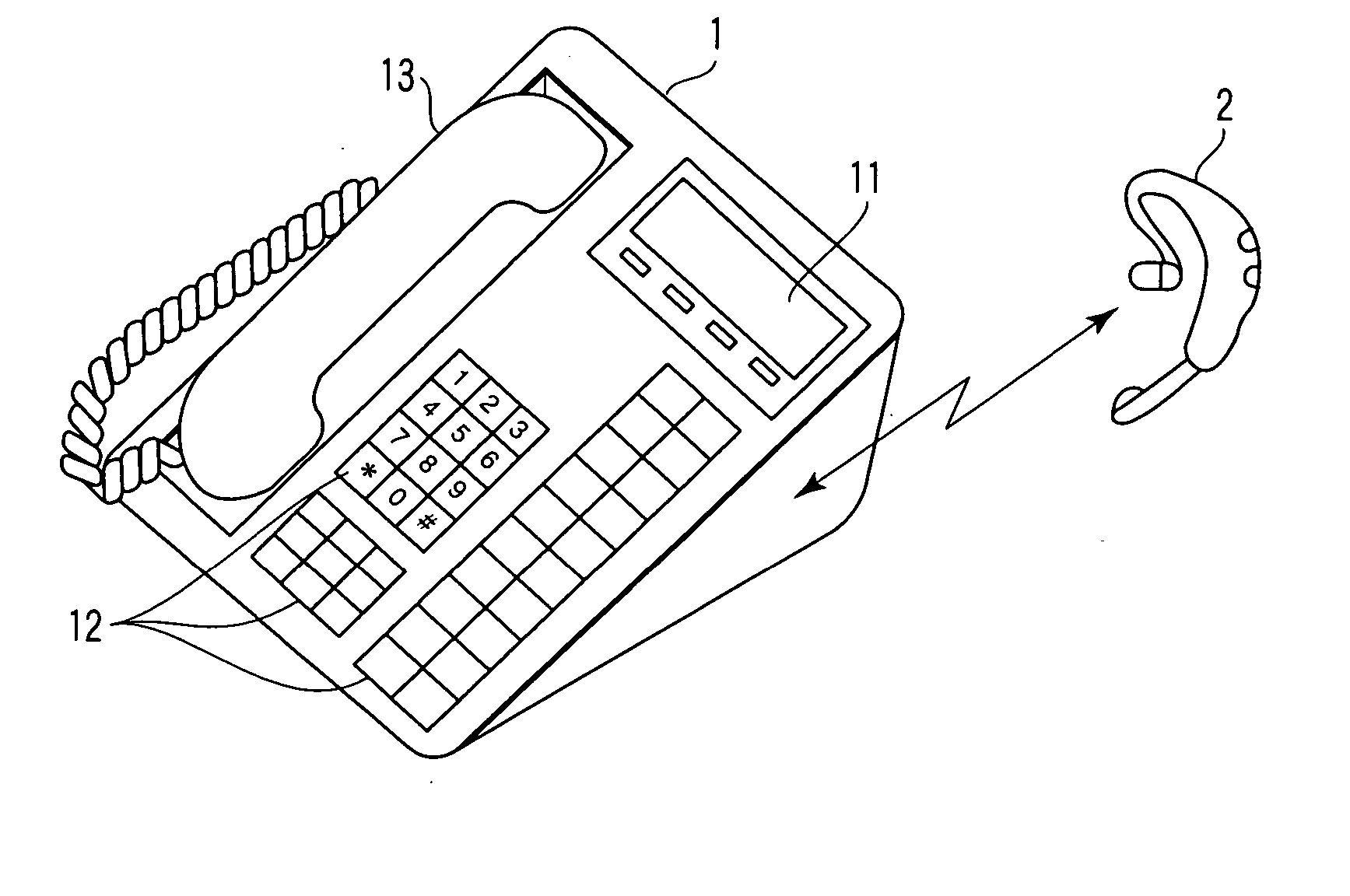
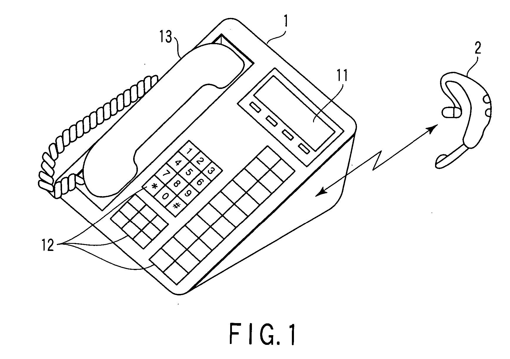
[0020]FIG. 1 is an outer appearance view showing a first embodiment of a telephone set and a BT headset regarding the present invention.
[0021] In FIG. 1, a BT headset 2 as a voice input / output device is connected to a telephone set main body 1 by radio. A display unit 11 using an LCD, etc., is arranged on a front panel part of the telephone set main body 1, further, a key matrix 12 composed of a dial key, a function key, etc., is disposed on a lower panel part of the display unit 11. A handset 13 with a loud-speaker and a microphone is arranged on the left side of the front panel part of the telephone set main body 1.
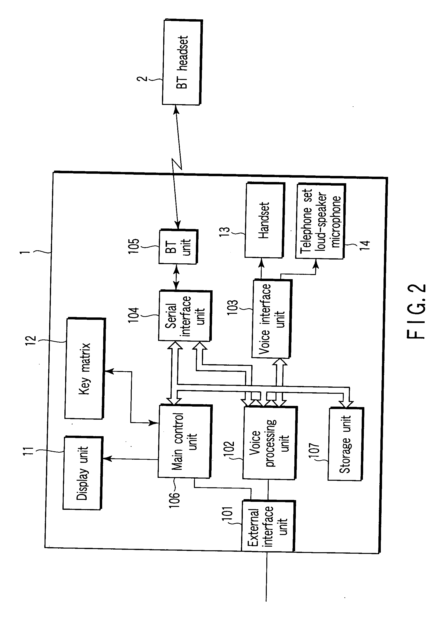
[0022] On the other hand, a circuit configuration of the telephone set main body 1 is described as follows. FIG. 2 is a block diagram showing the configuration.
[0023] As shown in FIG. 1, the telephone set main body 1 includes an external interface (I / F) unit 101, a voice processing unit 102, a voice interface unit 103, a serial interface unit (S I / O) 104, a BT unit 1...
second embodiment
[0041]FIG. 7 is a block diagram showing a configuration of a voice processing unit 102 in a second embodiment of the present invention. In FIG. 7, the same components as those of FIG. 4 are designated by the identical symbols and their detailed descriptions are eliminated.
[0042] That is to say, an echo canceller and an adder 32 are interposed between the output side of the volume controller 1022 and the input side of the transmission amplifier 1023.
[0043] The echo canceller 31 inputs an output signal from the volume controller 1022 to generate a signal to remove acoustic echoes added to the input signal from the transmission amplifier 1023. The output signal from the echo canceller 31 is added to the output signal from the serial interface 104 through the adder 32 then the acoustic echoes added to the transmission voice signal are reduced.
[0044] Next, operations in the aforementioned configuration will be described.
[0045] The BT headset 2 is miniaturized and lightened, so that s...
third embodiment
[0048]FIG. 8 is a block diagram depicting a configuration of a voice processing unit 102 in a third embodiment of the present invention. In FIG. 8, the same components as those of FIG. 4 are designated by the identical symbols and detailed descriptions are eliminated.
[0049] That is, a noise canceller 41 and an adder 42 are interposed on an input side of the transmission amplifier 1023.
[0050] The noise canceller 41 inputs an output signal from the serial interface unit 104 to generate a signal to remove noises added to the input signal to the transmission amplifier 1023. The output signal from the noise canceller 41 is added to the output signal from the serial interface unit 104 by the adder 42 then the noises added to the transmission voice signal are reduced.
[0051] As given above, in the third embodiment, the transmission voice signal having been amplified by the transmission amplifier 1023 after the cancellation of the noises by the noise canceller 41, the noises added to the ...
PUM
 Abstract
Description
Claims
Application Information
 - R&D
- Intellectual Property
- Life Sciences
- Materials
- Tech Scout
- Unparalleled Data Quality
- Higher Quality Content
- 60% Fewer Hallucinations
Browse by: Latest US Patents, China's latest patents, Technical Efficacy Thesaurus, Application Domain, Technology Topic, Popular Technical Reports.
© 2025 PatSnap. All rights reserved.Legal|Privacy policy|Modern Slavery Act Transparency Statement|Sitemap|About US| Contact US: help@patsnap.com


