Compression system for integrated sensor devices

a compression system and sensor technology, applied in the field of image data compression system, can solve the problems of reducing the speed and performance of imaging devices, lossy compression, reducing a file, etc., and achieve the effect of improving the compression of images exhibiting, reducing the variation between numerical pixel signal values, and precise reconstruction of initial pixel signal values

Active Publication Date: 2007-06-07
MICRON TECH INC
View PDF9 Cites 193 Cited by
  • Summary
  • Abstract
  • Description
  • Claims
  • Application Information

AI Technical Summary

Benefits of technology

[0008] The invention provides a method and apparatus for improved compression of images exhibiting low pixel variations where images are characterized by a strong correlation between one pixel and its immediate neighbors.
[0009] One embodiment provides for the use of linear prediction differential residual calculations to reduce variation between numerical pixel signal values. Differential residuals are classified into categories, where each category describes an ordered range of differential residual values. Frequency of occurrence of each differential residual within a given range is determined and-compiled into an ordered list of categories with most frequent residuals, next most frequent residuals and so on to the category with the least number of residuals. A variable length coding table that has the same list of ordered categories is selected from a set of stored variable length coding tables. Once a variable length coding table is selected, each residual is mapped into a variable length codeword associated with a category value along with an offset value. The offset value describes the position of the particular pixel signal value to be encoded within the ordered range associated with each category. Precise reconstruction of the initial pixel signal value can be achieved using a category identifier, a known range associated with a category and a range position offset value. Each mapped variable length codeword and associated range position offset value is sent to a serializer on the imager and then to a transmission unit.

Problems solved by technology

Larger amounts of imaging data reduces speed and performance of imaging devices.
Lossless compression is generally the technique of choice for text or spreadsheet files, where losing words or financial data could pose a problem.
Lossy compression, on the other hand, reduces a file by permanently eliminating certain information, especially redundant information.
Also, many applications require the use of lossless compression due to additional design constraints.
For example, remote endoscopy units in medical imaging applications have both hardware area and available bandwidth constraints.
Also, regulatory issues (e.g., FDA approval) will almost certainly be more complex in the with the use of lossy data compression, therefore data loss is undesirable.
Accordingly, size, area and other constraints adversely affect speed and efficiency of conventional imaging systems.

Method used


Image

  • Compression system for integrated sensor devices
  • Compression system for integrated sensor devices
  • Compression system for integrated sensor devices

Examples


Embodiment Construction

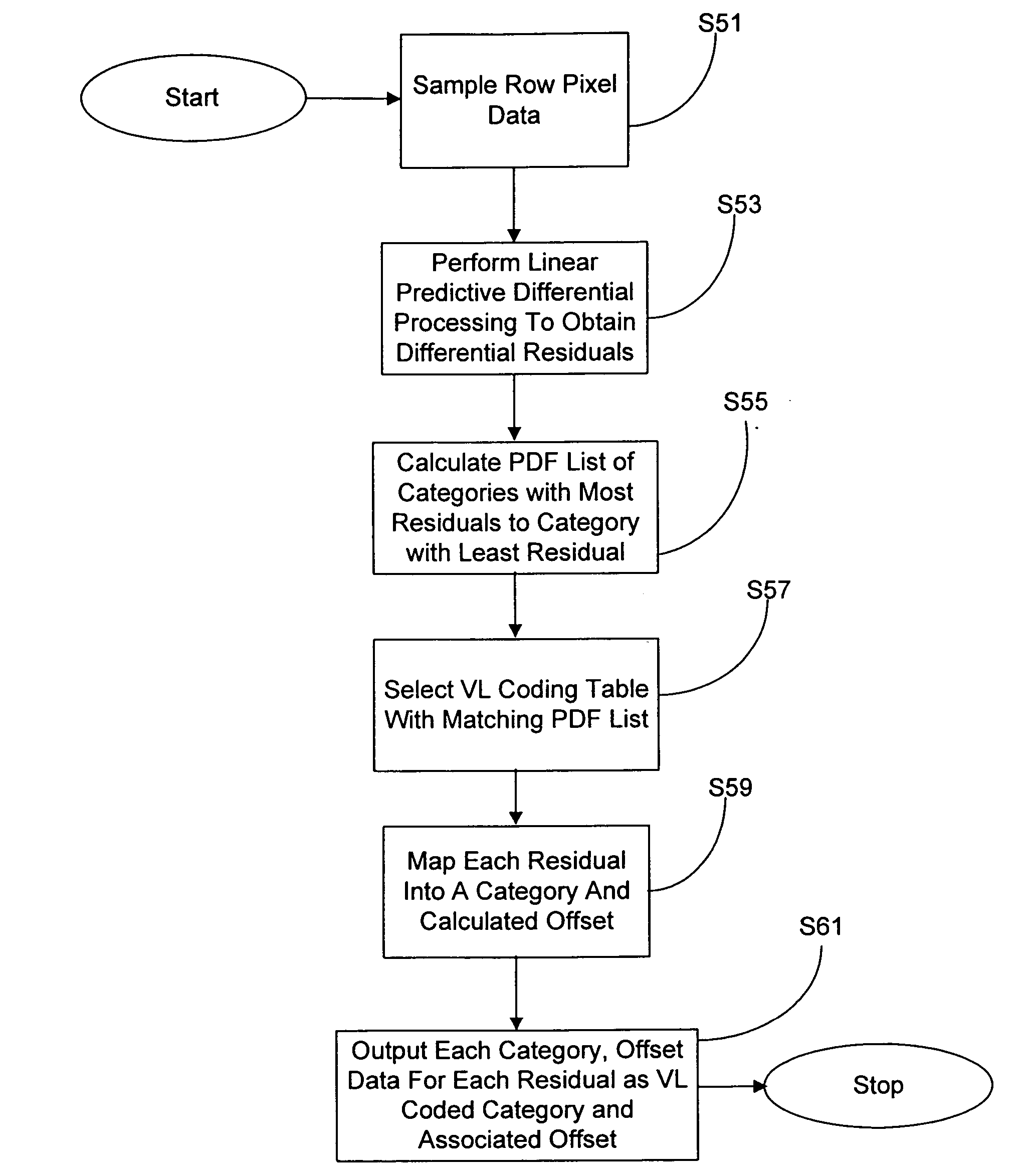
[0023] The invention uses adaptive lossless data compression to increase performance of imager sensors. Image data can be manipulated into symbols exhibiting low entropy or variation that can be compressed using adaptive lossless data compression to achieve compression ratios that are between a factor of two and three.

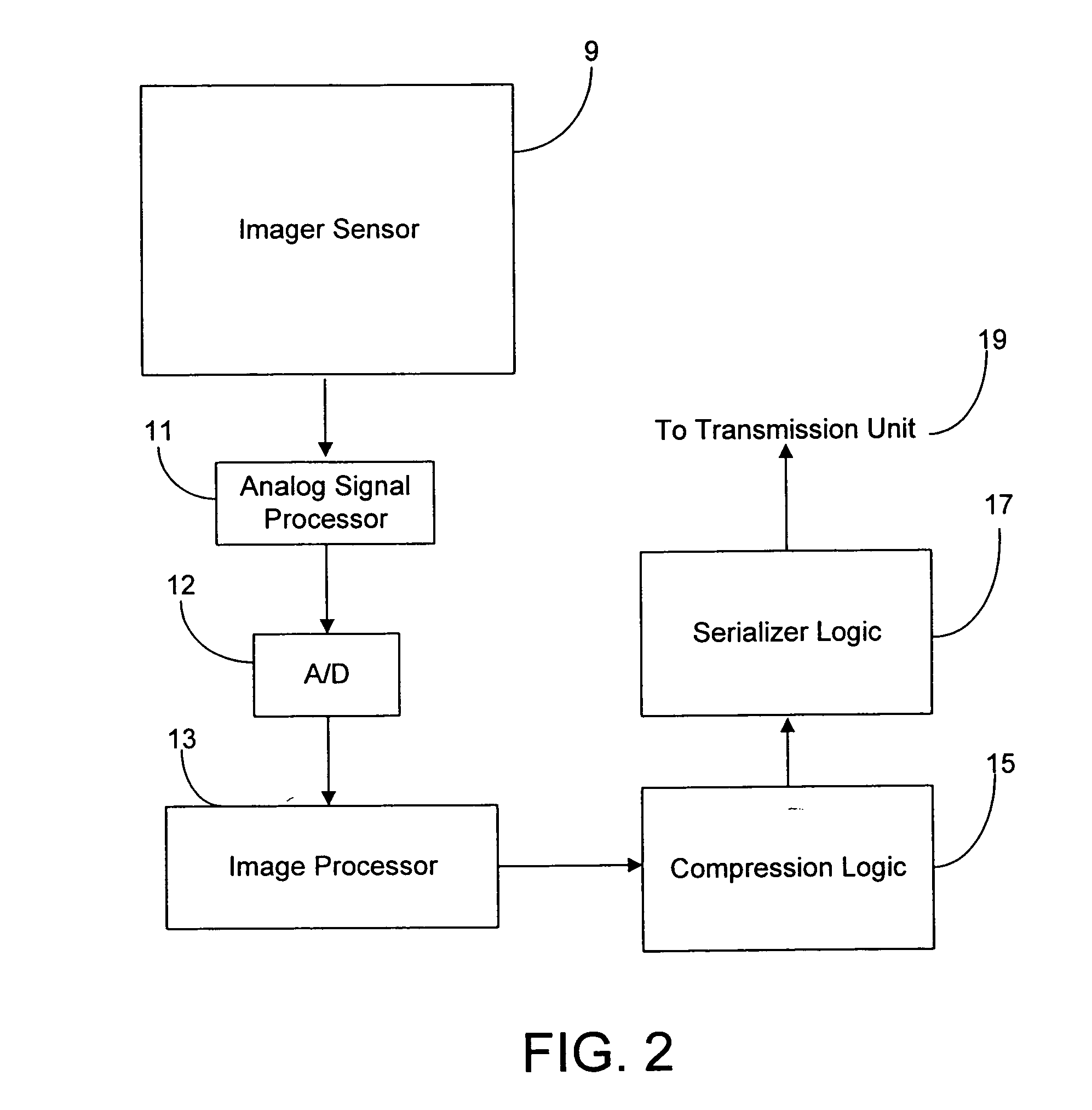
[0024] A variety of advantages are obtained by the use of efficient compression using adaptive lossless data techniques and minimized hardware design. For example, there is an increase in available bandwidth in a given transmission channel. Also, as more information can be represented in a fewer number of bits, the invention allows an increase in the overall throughput of transmitted data and a reduction of power consumption by constant throughput. The invention also has the ability to provide an error resilience capacity in the transmission system. In other words, the increased bandwidth can be used to build in error correction to account for channel transmission err...


PUM


Abstract

An imaging system incorporating adaptive compression which includes determining linear predictive differential residuals from an imager array pixel row. The differential residuals are classified into categories, each category having a range of differential residuals associated with it. The categories are analyzed to produce an ordered list having categories with most to least frequent residuals falling within a respective residual range associated with a respective category. The ordered list is then used to select a variable length encoding table with a matching ordered list. Variable length encoded category and range position offset data is output to a serializer unit, where the range position offset refers to a position in a range associated with a particular category.

Description

FIELD OF THE INVENTION [0001] The present invention relates generally to improved semiconductor imaging devices, and in particular to a compression system for image data transfer. BACKGROUND OF THE INVENTION [0002] As imaging technology has evolved, the density of imaging data has increased. Larger amounts of imaging data reduces speed and performance of imaging devices. Accordingly, a variety of approaches have been developed to improve the speed of imaging systems. [0003]FIG. 1 shows a block diagram of a conventional integrated sensor imager device fabricated on a chip. An imaging sensor 1 with an array of pixels transmits analog pixel signals to a sample and hold analog signal processing circuit 2. The analog output signals from circuit 2 are digitized in an analog to digital converter 3 and the digital signals are processed in an image processor 4. Imaging data is read out of the processor 4 and sent to a serializer 5. The serializer 5 sends imaging data to a transmission unit 7...

Claims


Application Information

Patent Timeline
Patent Type & Authority Applications(United States)
IPC IPC(8): G06K9/36G06K9/46H04N7/26H04N7/30H04N7/46
CPCH04N19/13H04N19/90H04N19/593H04N19/60
Inventor VENKATARAMAN, KARTIK
Owner MICRON TECH INC
Why Eureka
Try Eureka