Communication control method

a communication control and control method technology, applied in the direction of radio transmission, data switching by path configuration, electrical equipment, etc., can solve the problems of difficult to achieve the goal of the relay device, excessive load applied, and inability to efficiently conduct communications as an original obj

Inactive Publication Date: 2007-06-07
FUJITSU LTD
View PDF3 Cites 32 Cited by
  • Summary
  • Abstract
  • Description
  • Claims
  • Application Information

AI Technical Summary

Benefits of technology

[0029] The present invention enables the communication control corresponding to the purpose of the communication by assigning the group information

Problems solved by technology

Therefore, if the data are randomly transferred to other devices, an excessive load is applied to a relay device that relays the data, and it might be hard to accomplish an aim of this relay device.
For example, if dynamic image (moving picture) data targeting at a TV conference etc are transferred to a device targeting at a chat through the communication of text data, there is concern about such a point that the communications as an original object can not be e

Method used


Image

  • Communication control method
  • Communication control method
  • Communication control method

Examples


first embodiment

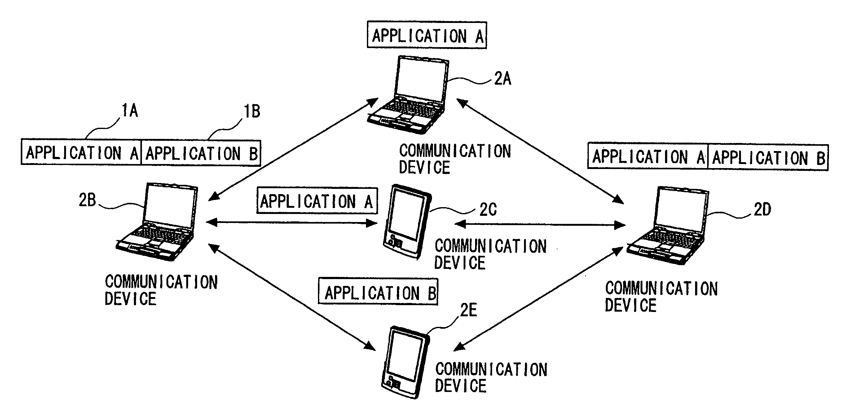
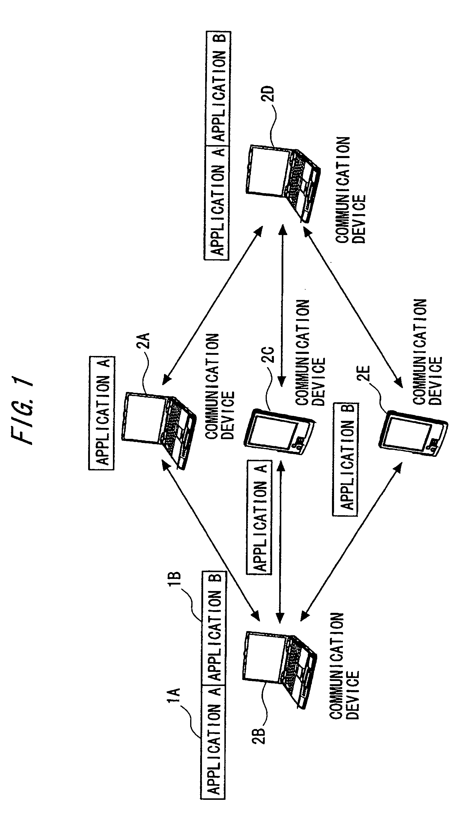
[0051] An embodiment of the present invention will hereinafter be described with reference to the drawings. FIG. 1 is a view showing an outline of architecture of an ad hoc communication system of the present invention. The present system is configured by an aggregation of communication devices 2A-2E on which one or more communication applications 1A, 1B operate. In the present system, the communication devices (wireless terminals) 2A-2E perform communications within a radio-wave reachable range and configure a temporary network (an ad hoc network), wherein the communications are carried out. Bidirectional arrowheads in FIG. 1 imply that the devices disposed at both ends of the arrowed line can perform the direct communications (namely, the devices exist within the radio-wave mutually reachable range). With this configuration, for example, the communication device 2B and the communication device 2D are unable to conduct the direct communications because of the radio waves being unre...

working example

[0132] Shown as below is a working example in a case where the present invention is applied to the communication control in an IPv6 (Internet Protocol version 6) network. The IP address is, however, described in an IPv4 format for simplifying the notation. In this example, a scheme that only the device executing the application of the same group is utilized as the relay device, is actualized by the communication control. To specific, a routing table different for every group is generated by utilizing and then extending OLSR (Optimized Link State Routing protocol) defined as a principal routing protocol in the ad hoc network, whereby the relay process corresponding to the group is actualized.

[0133]FIG. 13 depicts a system architecture in the present working example. In the present working example, the ad hoc network is configured by four pieces of communication equipment such as the communication devices 2A trough 2D, wherein any one or both of an application performing a dynamic-im...


PUM


Abstract

Group information is assigned for each communication object and communication data is transmitted by adding the group identifier, thereby realizing a communication control in accordance with the communication object. That is. when a communication device performing radio communication by constituting an ad-hoc network with a plurality of devices communicates with a destination device via at least one of the devices constituting the ad-hoc network, the communication device acquires group information assigned to the communication group having the common object with this communication, references a communication control data table containing communication control information for each of the group information so as to acquire the communication control information corresponding to the group information, adds the group information to the communication information to be transmitted to the destination device so as to generate communication data, identifies a device which relays the communication according to the communication control information, and transmits the communication data to this relay device.

Description

CROSS-REFERENCE TO RELATED APPLICATION [0001] This is a continuation of Application PCT / JP2004 / 007938, filed on Jun. 7, 2004, now pending, the contents of which are herein wholly incorporated by reference.BACKGROUND OF THE INVENTION [0002] The present invention relates to a technology of generating communication control information corresponding to a group that utilizes a communication application. [0003] Over the recent years, as devices have been downsized and decreased in their weights owing to developments of micro device technologies, there have increasingly been demands for utilizing communication services in every scene of life including an at-the-mobile-destination scene or an on-moving scene while carrying the device. It is, however, required that base stations be installed with a high density over a wide range in order to meet the demands in existing communication systems, and it is a large obstacle against the actualization to require a tremendous amount of costs for impr...

Claims


Application Information

Patent Timeline
IPC IPC(8): H04B7/00H04L12/28
CPCH04L12/2854
Inventor IWAMOTO, KATSUNORISATO, YOSHIHARUYAMAMURA, SHINYA
Owner FUJITSU LTD
Why Eureka
Try Eureka