Ultra low power wake-up circuit

Active Publication Date: 2007-06-07
CARDINAL HEALTH IRELAND UNLTD
View PDF8 Cites 18 Cited by
  • Summary
  • Abstract
  • Description
  • Claims
  • Application Information

AI Technical Summary

Benefits of technology

[0013] This summary is provided to introduce a selection of concepts in a simplified form that are further described below in the Detailed Description. This summary is not inten

Problems solved by technology

Even in their sleep state, these low power devices still have leakage currents.
Even small leakage currents can significantly impact battery life.
Leakage currents present a signif

Method used


Image

  • Ultra low power wake-up circuit
  • Ultra low power wake-up circuit
  • Ultra low power wake-up circuit

Examples


Embodiment Construction

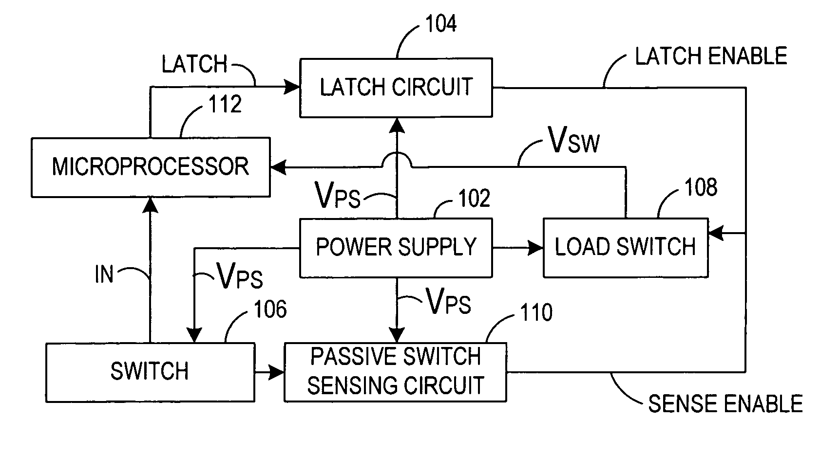
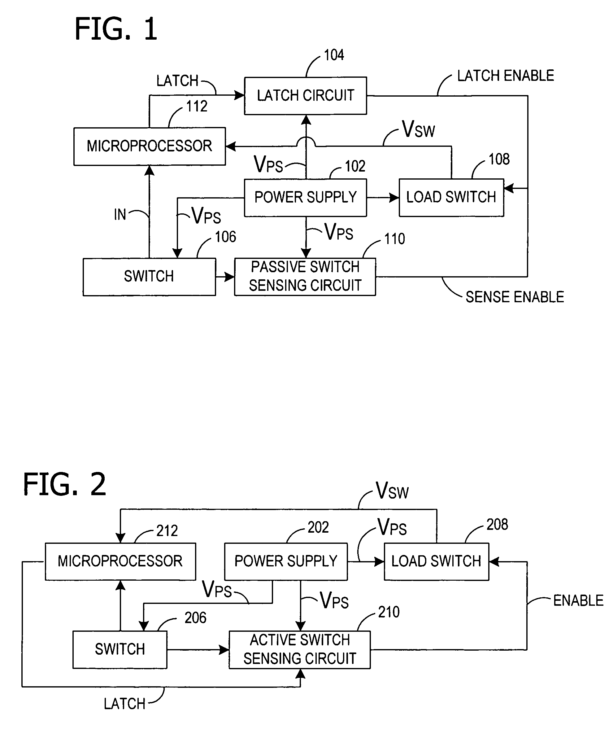
[0020] In one embodiment, the present invention is an ultra low power wake-up circuit which draws essentially no power while waiting for a user input. Power is supplied to components of the wake-up circuit directly from a power supply and power is selectively supplied to device components through a load switch. The wake-up circuit is adapted to wake up the device in response to any number of events, such as a user pushing any of the input keys on the device's user interface, removing or replacing a component from its docking position on the device, receiving a signal from another device, or opening or closing the cover of the device. For example, in the case of a clinical thermometer such as a predictive or infrared thermometer, the device should have the capability to wake up whenever the temperature probe is removed or replaced, whenever the probe cover is removed or replaced, whenever a button on the device is pressed, or whenever a device cover is opened or closed. The thermomet...


PUM


Abstract

An apparatus for selectively enabling power including a power supply, and a device having a controller and an input activated by a user. The controller is selectively powered by the power supply. While the device is in a sleep state, a sensing circuit senses activation of the input by the user and enables the power supply to provide power to the controller in response to the sensed activation of the input by the user. A latch circuit causes the power supply to continue to provide power to the controller. The controller is responsive to the sensed activation of the input by the user for enabling the latch circuit and for disabling the latch circuit, thereby reentering the device into a sleep state.

Description

FIELD OF THE INVENTION [0001] The present invention generally relates to electronic devices having a sleep mode. In particular, the invention relates to a method and apparatus for placing an electronic device in a power conserving sleep mode and waking it upon an input from a user. BACKGROUND OF THE INVENTION [0002] For many years, battery-operated devices have been popular. In early devices, the user was required to power down the device or manually disconnect the battery from the device via a switch so that the device did not drain the battery when not in use. [0003] There are now a number of electronic devices that have been developed to operate with low power so that completely isolating the batteries via a user-operated switch is not necessary. More recent electronic devices have also been designed with a sleep state wherein the microprocessor of the device will use a switch to cut power to nonessential elements of the device thereby saving additional energy by eliminating the ...

Claims


Application Information

Patent Timeline
IPC IPC(8): G06F1/26
CPCG01K2215/00G06F1/26G06F1/32H02M1/16
Inventor PRICE, JEFFREY E.BISCH, MICHAEL E.HERNANDEZ, HECTORFORREST, JEFFREY E.
Owner CARDINAL HEALTH IRELAND UNLTD
Why Eureka
Try Eureka