Independent pilot fuel control in secondary fuel nozzle

a pilot fuel and secondary fuel technology, applied in the ignition of turbine/propulsion engine, engine starter, engine lighting and heating apparatus, etc., can solve the problem of high nox emissions

Active Publication Date: 2007-06-14
GENERAL ELECTRIC CO
View PDF11 Cites 27 Cited by
  • Summary
  • Abstract
  • Description
  • Claims
  • Application Information

AI Technical Summary

Problems solved by technology

), the high temperatures of diffusion combustion result in relatively high NOx emissions.

Method used


Image

  • Independent pilot fuel control in secondary fuel nozzle
  • Independent pilot fuel control in secondary fuel nozzle
  • Independent pilot fuel control in secondary fuel nozzle

Examples


Embodiment Construction

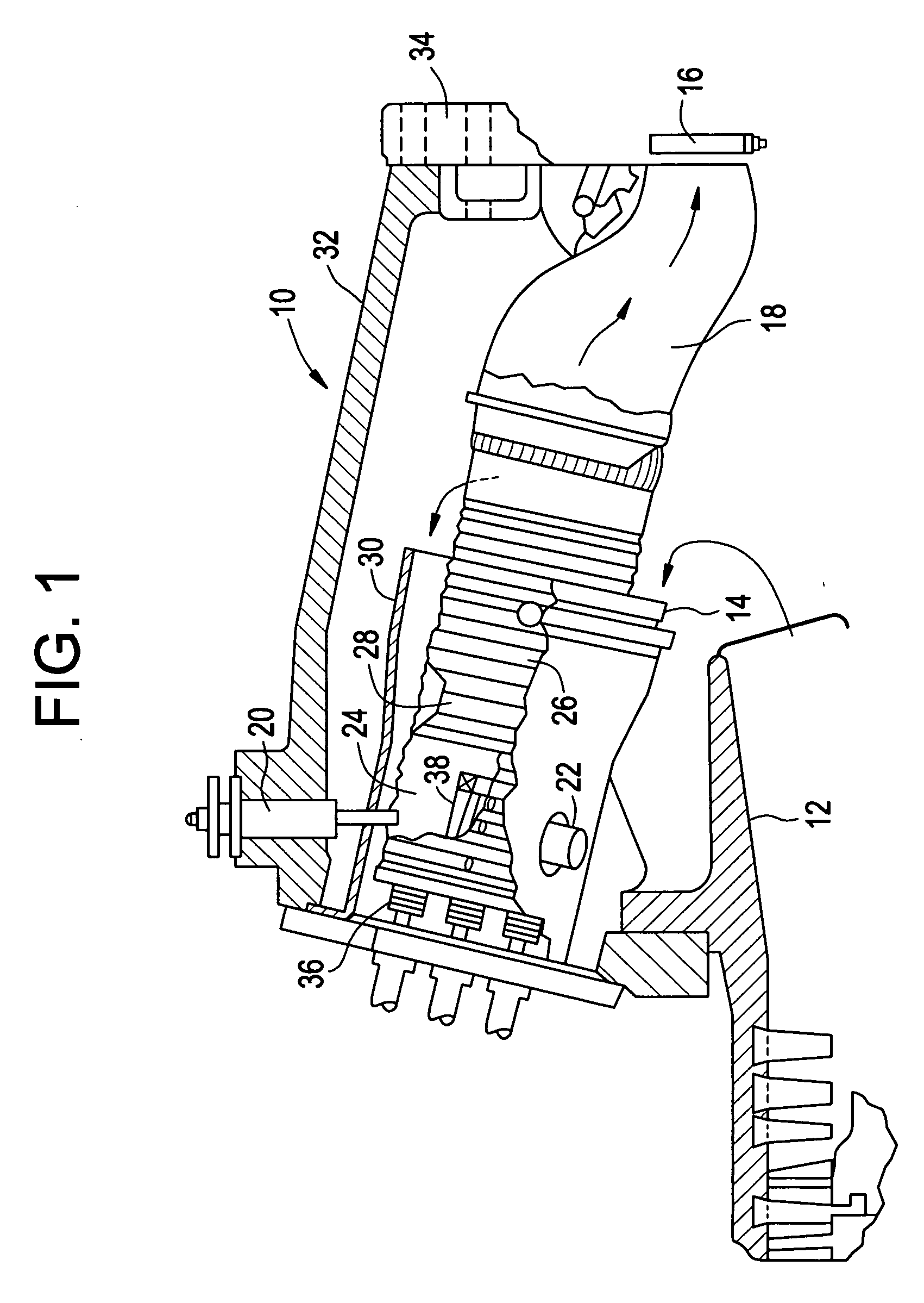
[0015] Referring to FIG. 1, a gas turbine 10 (partially shown) includes a compressor 12 (also partially shown), a plurality of combustors 14 (one shown), and a turbine section represented here by a single blade 16. Although not specifically shown, the turbine is drivingly connected to the compressor 12 along a common axis. The compressor 12 pressurizes inlet air which is then reverse flowed to the combustor 14 where it is used to cool the combustor and to provide air to the combustion process.

[0016] As noted above, the plurality of combustors 14 are located in an annular array about the axis of the gas turbine. A transition duct 18 connects the outlet end of each combustor 14 with the inlet end of the turbine to deliver the hot products of combustion to the turbine in the form of an approved temperature profile.

[0017] Each combustor 14 may comprise a primary or upstream combustion chamber 24 and a secondary or downstream combustion chamber 26 separated by a venturi throat region 2...


PUM


Abstract

Disclosed herein is a fuel nozzle. The fuel nozzle includes a first fuel introduction location, a second fuel introduction location, and fuel passages. The first fuel introduction location is located radially about the fuel nozzle and is connected with a fuel passage. The second fuel introduction location is located at an end of the fuel nozzle and is connected with another fuel passage such that the fuel passage connected to the first fuel introduction location is separate from the fuel passage connected to the second fuel introduction location.

Description

TECHNICAL FIELD [0001] This application relates generally to gas turbines, and more specifically, to a secondary fuel nozzle for a gas turbine combustor with individually controlled fuel circuits intended to provide optimum combustion system emissions concentrations. BACKGROUND OF THE INVENTION [0002] A gas turbine combustor is essentially a device used for mixing fuel and air, and burning the resulting mixture. Gas turbine compressors pressurize inlet air which is then turned in direction or reverse flowed to the combustor where it is used to cool the combustor and also to provide air to the combustion process. Multiple combustion chamber assemblies may be utilized to achieve reliable and efficient turbine operation. Each combustion chamber assembly comprises a cylindrical combustor liner, a fuel injection system, and a transition piece that guides the flow of the hot gas from the combustor liner to the inlet of the turbine section. Gas turbines for which the present fuel nozzle de...

Claims


Application Information

Patent Timeline
Patent Type & Authority Applications(United States)
IPC IPC(8): F23R3/20
CPCF23C6/047F23D2209/30F23D2900/00008F23D2900/00015F23D2900/14004F23L7/002F23R3/346
Inventor VANDALE, DANIEL D.SIMONS, DERRICKNEGRONI, ALBERTO JOSEROMOSER, CAREY
Owner GENERAL ELECTRIC CO
Why Eureka
Try Eureka