
Compliant abradable sealing system and method for rotary machines

a sealing system and rotary compressor technology, applied in the field of rotary machines, can solve the problems of poor efficiency, relatively high leakage within the device, and poor fit between internal components of the rotary pump or compressor

Inactive Publication Date: 2007-06-14
GENERAL ELECTRIC CO
View PDF26 Cites 37 Cited by
  • Summary
  • Abstract
  • Description
  • Claims
  • Application Information

AI Technical Summary

Benefits of technology

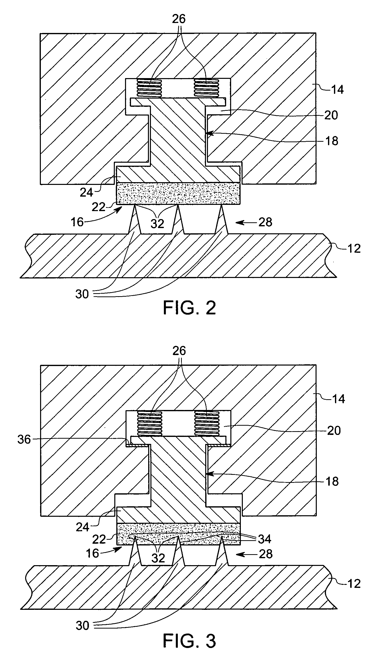
[0009] In accordance with another aspect of the present invention, a method for improving performance of a rotary compressor includes disposing a rotor in a stator housing. A compliant abradable sealing system is disposed between the rotor and the stator housing and configured to control leakage of a fluid flowing through the compressor. A radially movable sealing element is coupled to at least one biasing member within the stator housing. A mating radially fixed sealing element is coupled to the rotor. The radially fixed sealing element is rotated relative to the radially movable sealing element to form a plurality of permanent sealing grooves in the radially movable sealing element to form a zero-clearance labyrinth seal therebetween.

Problems solved by technology

A loosely-toleranced rotary pump or compressor may have a relatively poor fit between internal components and may therefore exhibit poor efficiency, with relatively high leakage occurring within the device from regions of high pressure to regions of lower pressure.
Fluid leakage through the rotary machines is generally undesirable for various reasons.
For example, fluid leakage between the rotor and a circumferentially surrounding casing of a compressor may lower the efficiency of the compressor leading to increased fuel costs.
Running clearances may deviate from design intent due to misalignment between rotor and casing, and during transients such as start-up, the rotor may expand relative to the casing or sweep through orbits, causing the rotor and stationary components to interfere (i.e., contact one another).
As a result, seal components, which are provided on the rotor as well as the stator, may be damaged.

Method used


Image

  • Compliant abradable sealing system and method for rotary machines
  • Compliant abradable sealing system and method for rotary machines
  • Compliant abradable sealing system and method for rotary machines

Examples


Embodiment Construction

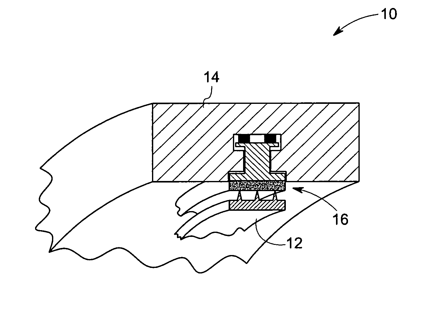
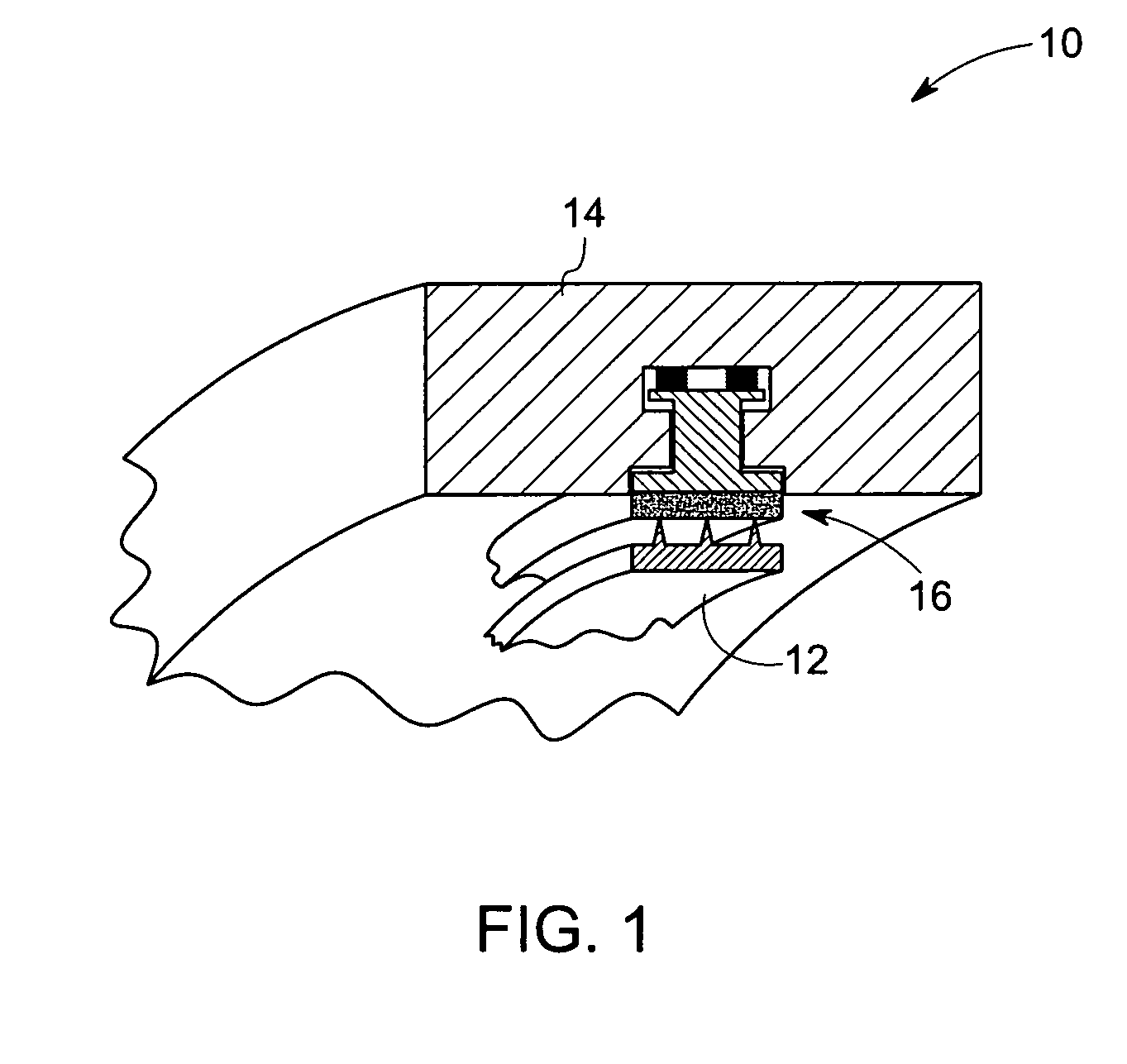
[0021] As discussed in detail below, aspects of the present invention provide a compliant abradable sealing system for a rotary machine having a radially movable sealing element configured to contact a mating radially fixed sealing element. The radially fixed sealing element is rotatable relative to the radially movable sealing element to form a plurality of permanent sealing grooves in the radially fixed sealing element or in the radially movable sealing element. During transient operating conditions of the rotary machine, the compliant abradable sealing system facilitates minimum clearance between a rotor and a stator casing. As a result, fluid leakage through the rotary machine is minimized and the overall efficiency is enhanced. Also disclosed is a method of operating the compliant abradable sealing system. Specific embodiments of the present invention are discussed below referring generally to FIGS. 1-8.

[0022] Referring to FIG. 1, a rotary machine (for example, a rotary compre...


PUM


Abstract

A method for operating a compliant abradable sealing system includes biasing a radially movable sealing element to contact a mating radially fixed sealing element. The radially fixed sealing element is rotated relative to the radially movable sealing element. The radially fixed sealing element is provided on a rotor. The radially movable sealing element is provided in a stator housing. The radial movement of the movable sealing element is limited by a stopping device provided between the movable sealing element and the stator housing. A plurality of permanent sealing grooves are formed in the radially movable sealing element to form a zero-clearance labyrinth seal.

Description

BACKGROUND [0001] The invention relates generally to rotary machines, and in particular to a compliant abradable sealing system for a rotary compressor, and method for a operating a compliant abradable sealing system for facilitating a minimum dynamic clearance during steady state and transient operating conditions of a rotary compressor. [0002] Efficiency of rotary devices utilized for pumping a fluid or compressing a vapor (e.g. gas) depends upon the internal tolerances of the components comprising the device. A loosely-toleranced rotary pump or compressor may have a relatively poor fit between internal components and may therefore exhibit poor efficiency, with relatively high leakage occurring within the device from regions of high pressure to regions of lower pressure. The traditional approach to this situation is to decrease the amount of clearance on these critical interfaces. [0003] Sealing systems are used in rotary machines such as turbines, compressors, or the like to redu...

Claims


Application Information

Patent Timeline
IPC IPC(8): F16J15/447
CPCF16J15/445
Inventor WOLFE, CHRISTOPHER EDWARDGHASRIPOOR, FARSHADSALEHI, MOHSENBRISSON, BRUCE WILLIAM
Owner GENERAL ELECTRIC CO
Learn More