Lighting-drive device, light source device, and display device

Inactive Publication Date: 2007-06-14
SONY CORP
View PDF5 Cites 3 Cited by
  • Summary
  • Abstract
  • Description
  • Claims
  • Application Information

AI Technical Summary

Benefits of technology

[0021] According to the above-described respective configurations, the part that includes the following elements is constructed as one single component unit integrally: the lighting-drive circuit for driving a discharge lamp for the (steady) lighting thereof, the activation circuit for starting the lighting of the discharge lamp, and the activation operation detector for detecting the normality of operation of the activation circuit. The active operation detector employs a configuration in which a sensing member senses an induced voltage arising due to an activation current flowing in response to an activation voltage. In embodiments of the invention, the activation circuit and the activation operation detector are housed in the same single component as described above. Thus, the sensing member can be easily disposed at such an appropriate position in the single component as to be c

Problems solved by technology

In this case, the cause of the failure of the lighting of the HID lamp is involved in at least one of the HID lamp itself and the ignition circuit.
The coated conductive lead as the antenna line is a member obtained by coating a properly thin conductive lead with resin or the like, and therefore is difficult to fix at the required position as it is.
Accordingly, it is necessary to provide a mechanical holding component or the like for fixedly disposing the ante

Method used


Image

  • Lighting-drive device, light source device, and display device
  • Lighting-drive device, light source device, and display device
  • Lighting-drive device, light source device, and display device

Examples


Example

[0042] Before the description of a best mode (hereinafter, referred to as an embodiment) for carrying out the present invention, the background of the invention will be described below.

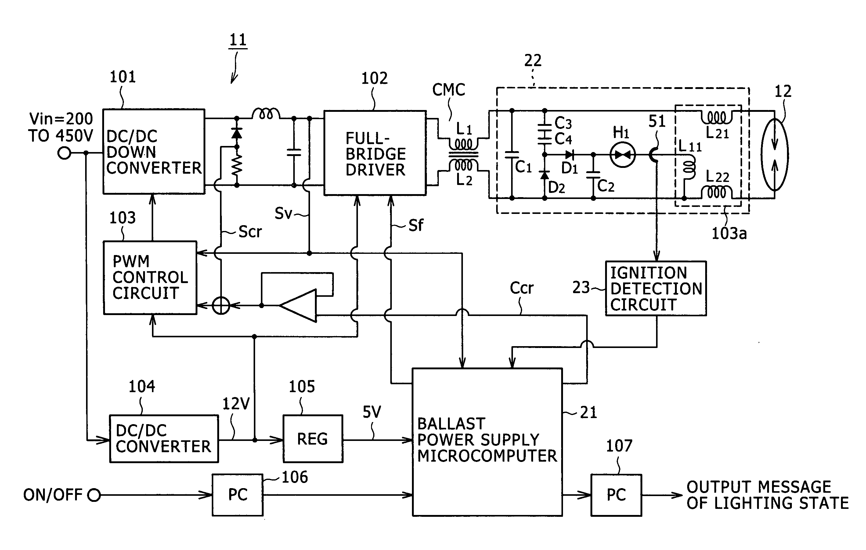
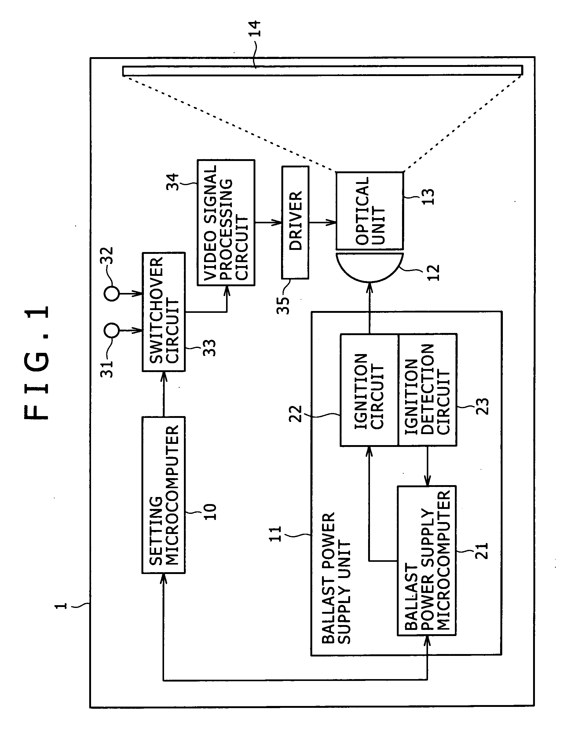
[0043]FIG. 18 shows a configuration example of an existing projector device 1. This diagram is to mainly show a configuration for driving a lamp 12 as a light source for the lighting thereof in the projector device 1.

[0044] An HID lamp is used for the lamp 12 as the light source in this device. Light emitted from the lamp 12 as the light source enters an optical unit 13. The optical unit 13 is configured to convert the incident light into color image light dependent upon a video signal, and project this color image light on the backside of a screen 14 in a magnified form. A user sees the screen 14 from the front side thereof, and thereby can view displayed images.

[0045] The lamp 12 is supplied with power from a ballast power supply unit 11 so as to be driven for the lighting thereof. The ballast po...


PUM


Abstract

A lighting-drive device includes: a lighting-drive circuit configured to drive a lamp for lighting of the lamp; an activation circuit configured to produce an activation voltage to be applied to the lamp in order to start lighting of the lamp; and an activation operation detector configured to be provided with a sensing member for sensing an induced voltage and output an operation state notification signal depending on a state of the induced voltage. The sensing member is provided on a circuit substrate on which the activation circuit is formed in such a manner as to be allowed to sense the induced voltage. The activation current flows in response to the activation voltage produced by the activation circuit. The operation state notification signal indicates whether or not the activation circuit has operated normally. The lighting-drive circuit, the activation circuit and the activation operation detector are integrated into one single component.

Description

CROSS REFERENCES TO RELATED APPLICATIONS [0001] The present invention contains subject matter related to Japanese Patent Application JP 2005-355122 filed with the Japanese Patent Office on Dec. 8, 2005, the entire contents of which being incorporated herein by reference. BACKGROUND OF THE INVENTION [0002] 1. Field of the Invention [0003] The present invention relates to a lighting-drive device for driving a lamp such as a high intensity discharged (HID) lamp for the lighting thereof, and to a light source device and a display device that include such a lighting-drive device. [0004] 2. Description of the Related Art [0005] An image display device such as a projector device includes a light source and modulates light emitted from the light source by a liquid crystal panel or the like based on video signals, so that the modulated light is projected on a screen in a magnified form and thus images are displayed. [0006] As this light source, an HID lamp is widely employed. Drive circuitry...

Claims


Application Information

Patent Timeline
IPC IPC(8): H05B41/36
CPCH05B41/04H05B41/02H05B41/24
Inventor KITTA, YOSHIMASAKOBAYASHI, KENICHIAKIHO, HITOSHI
Owner SONY CORP
Why Eureka
Try Eureka