
Saddle type vehicle and vehicle power unit

Active Publication Date: 2012-10-04
HONDA MOTOR CO LTD
View PDF11 Cites 0 Cited by
  • Summary
  • Abstract
  • Description
  • Claims
  • Application Information

AI Technical Summary

Benefits of technology

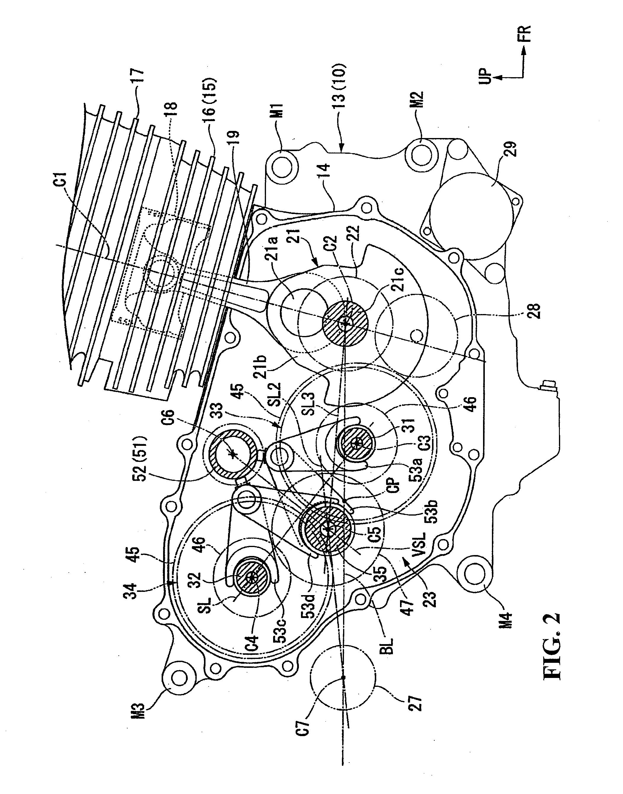
[0027]According to an embodiment of the present invention, in the power unit having a pair of main shaft and a pair of clutches, the height size of the crankcase can be made small by distributing or arranging the main shafts and the clutches on the front and rear sides. This ensures that a space for layout of an intake system and the like can be easily secured on the upper side of the crankcase, and the amount of downward projection of the crankcase can be suppressed.
[0028]According to an embodiment of the present invention, the main shafts and the clutches can be distributed (i.e., arranged) on the upper and lower sides between the crankshaft and the pivot shaft. Consequently, the distance from the crankshaft to the pivot shaft can be shortened, and the periphery of the power unit (and hence the vehicle body of the completed vehicle) can be formed to be compact in the back-and-forth direction.
[0029]According to an embodiment of the present invention, even in taking out power from the counter shaft to the outside of the power unit, the output part and the pivot shaft can be easily disposed close to each other, and the amount of swinging of the swing arm can be easily secured.
[0030]According to an embodiment of the present invention, the pivot shaft can be easily disposed rearwardly of the crankcase and at a height comparable to that of the crankshaft.
[0031]According to an embodiment of the present invention, the back-and-forth length of the crankcase can be made small by disposing the second clutch rather near the counter shaft side.
[0032]According to an embodiment of the present invention, the back-and-forth length of the space for containing the clutches, and hence of the crankcase, can be shortened, and the distance from the crankshaft to the pivot shaft can be shortened.

Problems solved by technology

Meanwhile, the vehicle power unit having a pair of main shafts and a pair of clutches on different axes as in the related art has a problem that since the space for layout of each of the shafts in it tends to be increased as compared with a power unit having main shafts and clutches in a coaxial fashion, it influences the vehicle body size when used as a power unit for a small-type vehicle (saddle type vehicle) such as a motorcycle.

Method used


Image

  • Saddle type vehicle and vehicle power unit
  • Saddle type vehicle and vehicle power unit
  • Saddle type vehicle and vehicle power unit

Examples


Embodiment Construction

[0047]Now, an embodiment of the present invention will be described below referring to the drawings. Incidentally, the directions such as forward, rearward, leftward (left) and rightward directions in the following description are the same as those with reference to the vehicle described below, unless otherwise specified. Besides, at appropriate parts in the drawings used in the following description, arrow FR indicative of the front side of the vehicle, arrow LH indicative of the left-hand side of the vehicle and arrow UP indicative of the upper side of the vehicle are shown.

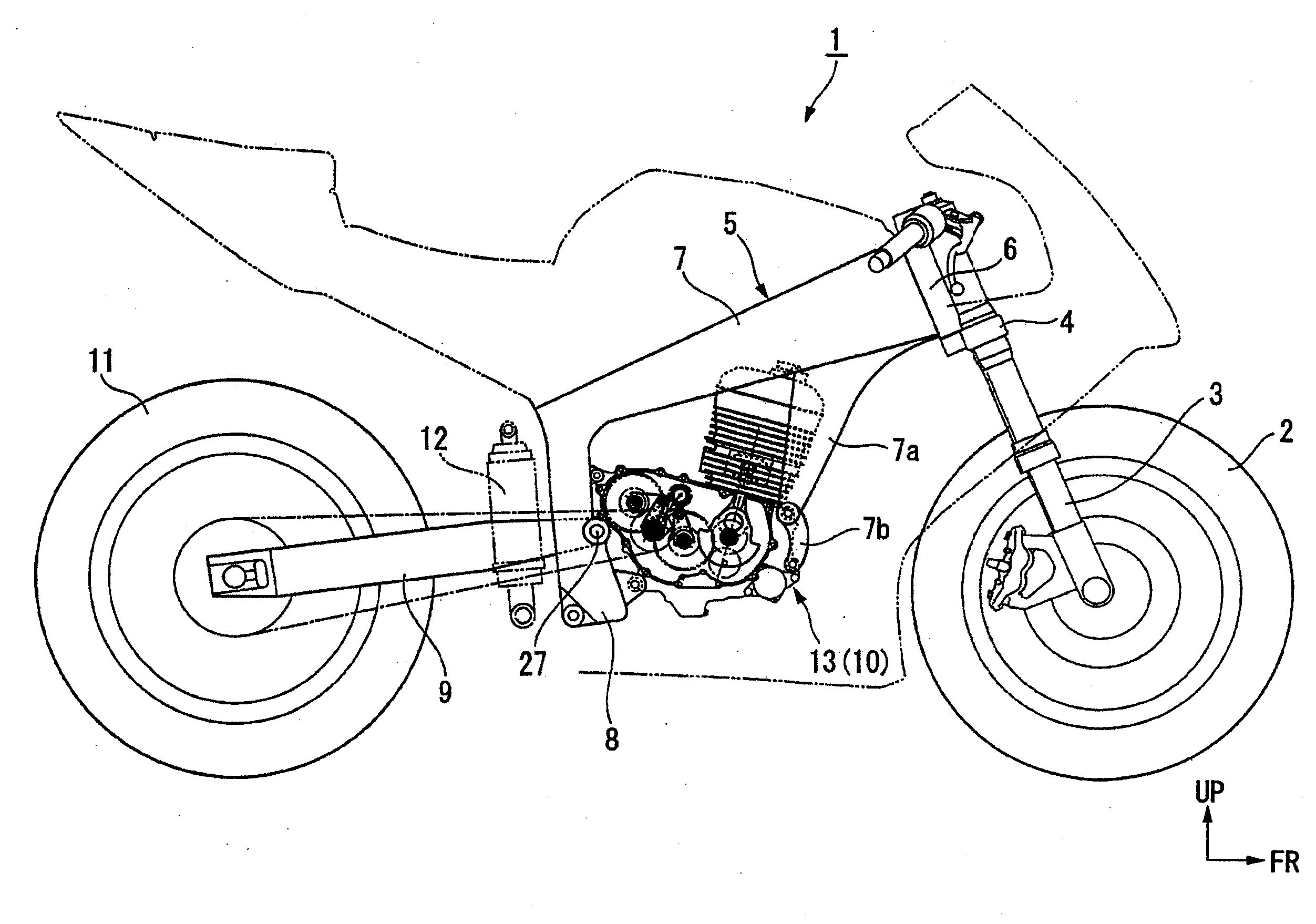
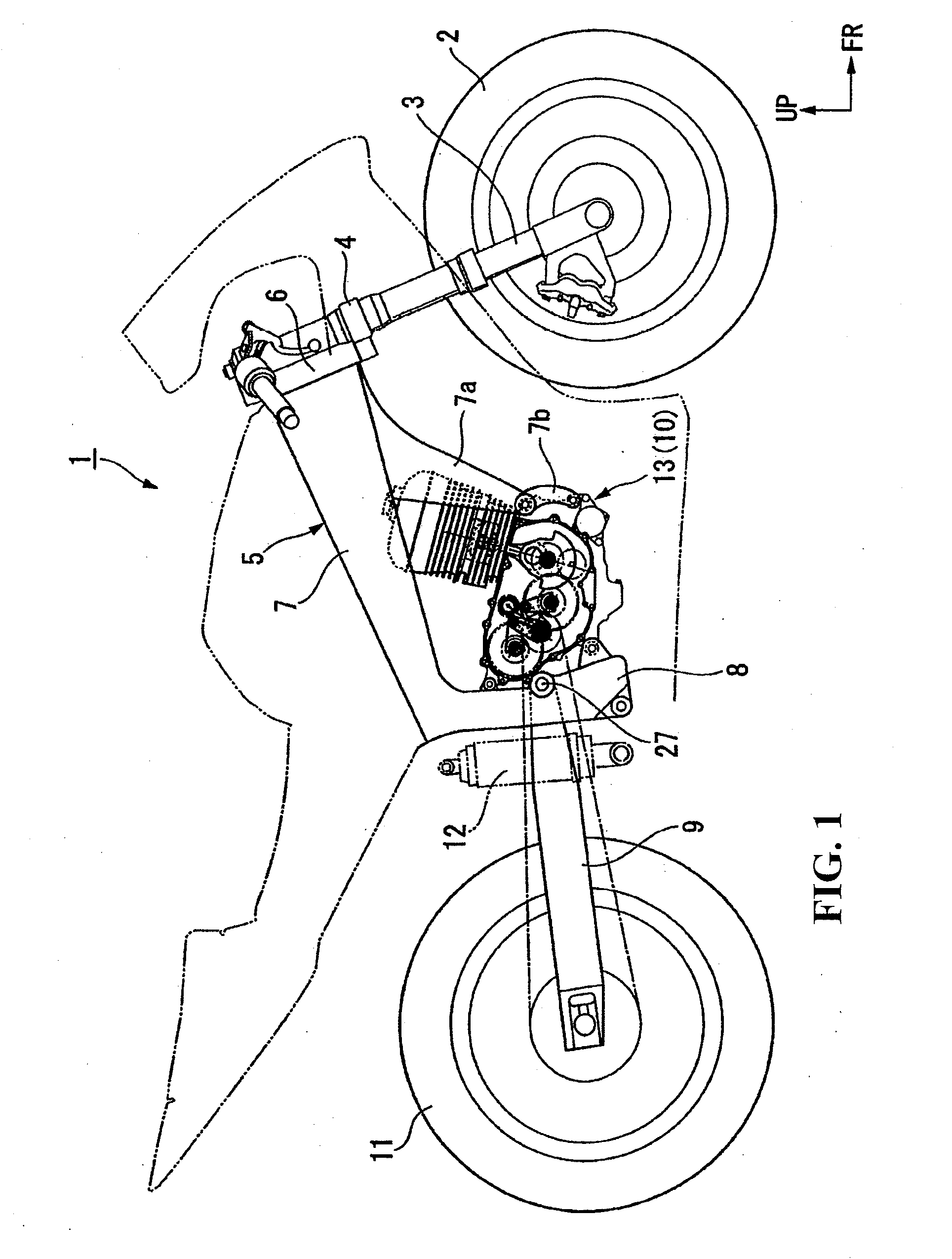
[0048]In a motorcycle (saddle type vehicle) 1 shown in FIG. 1, a front wheel 2 is rotatably borne on a front fork 3, which is steerably supported at an upper portion thereof on a head pipe 6 at a front end portion of a body frame 5 through a steering stem 4. A main frame 7 obliquely extends downwardly rearward from the head pipe 6, and a pivot frame 8 is connected at an upper end portion thereof to a rear end p...


PUM


Abstract

A saddle type vehicle having mounted thereon a power unit is provided with a twin clutch type transmission including a pair of main shafts and a pair of clutches along different axes, to enable a compact layout of axes and a reduction in size of the unit and its surroundings. The axis center (first main axis) of a first main shaft is disposed rearwardly of the axis center (crank axis) of a crankshaft and forwardly of the axis center (counter axis) of a counter shaft, whereas the axis center (second main axis) of a second main shaft is disposed rearwardly of the axis center (counter axis) of the counter shaft and forwardly of the axis center (pivot axis) of a pivot shaft.

Description

CROSS-REFERENCE TO RELATED APPLICATION[0001]The present application claims priority under 35 U.S.C. §119 to Japanese Patent Application Nos. 2011-077074 and 2011-077249, filed on Mar. 31, 2011, respectively, each of the above-identified applications is incorporated by reference.BACKGROUND OF THE INVENTION[0002]1. Field of the Invention[0003]The present invention relates to a saddle type vehicle having mounted thereon a power unit which includes a twin clutch type transmission having main shafts and clutches along different axes.[0004]2. Description of Background Art[0005]Hitherto, there has been known a vehicle power unit provided with a twin clutch type transmission wherein gear trains for a plurality of gear speeds established selectively are provided between a pair of main shafts disposed in parallel to each other and a counter shaft having an axis parallel to the main shafts, and wherein the pair of main shafts are coaxially provided with respective clutches for permitting / inter...

Claims


Application Information

Patent Timeline
IPC IPC(8): F16H3/08
CPCF16H3/006F16H3/16Y10T74/19279Y10T74/19223Y10T74/19233B62K25/283
Inventor FUJIMOTO, YASUSHIMIZUNO, KINYATSUKADA, YOSHIAKIOZEKI, TAKASHINAKAMURA, KAZUHIKONAKAGAWA, MITSUO
Owner HONDA MOTOR CO LTD
Learn More