Supporting structure for rotary shaft

Inactive Publication Date: 2020-06-04
TOYOTA JIDOSHA KK
View PDF0 Cites 0 Cited by
  • Summary
  • Abstract
  • Description
  • Claims
  • Application Information

AI Technical Summary

Benefits of technology

[0011]Thus, according to the exemplary embodiment of the present disclosure, the first bearing is fastened on the rotary shaft together with the rotary member by the fastening member. For example, given that a nut is adopted as the fastening member, the first bearing is fastened on the rotary shaft while being brought into abutment on the rotary member by screwing the nut onto the rotary shaft. According to the embodiment of the present disclosure, therefore, a distance between the first bearing and the second bearing, that is, a support span of the rotary shaft in the axial direction can be shortened compared to the conventional structure in which the bearing is disposed axially outer side of the nut. For this reason, a bending moment applied to the rotary shaft can be reduced to prevent flexure of the rotary shaft.
[0012]According to the embodiment of the present disclosure, specifically, a support span of the rotor shaft on which the rotor of the motor is mounted can be shortened. Therefore, a bending moment applied to the rotor shaft

Problems solved by technology

Therefore, the rotor shaft may be subjected to a relatively large a bending moment.
However, if the support span of the rotor shaft is too long, the air gap in the motor is n

Method used


Image

  • Supporting structure for rotary shaft
  • Supporting structure for rotary shaft
  • Supporting structure for rotary shaft

Examples


Example

[0021]Preferred embodiments of the present disclosure will now be explained with reference to the accompanying drawings.

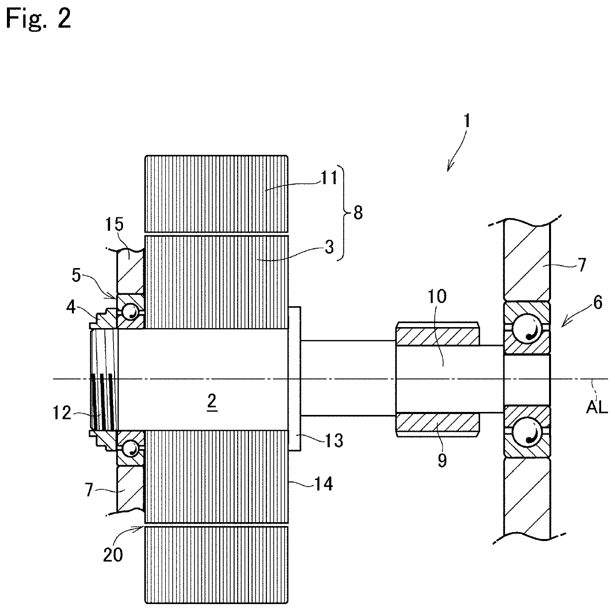
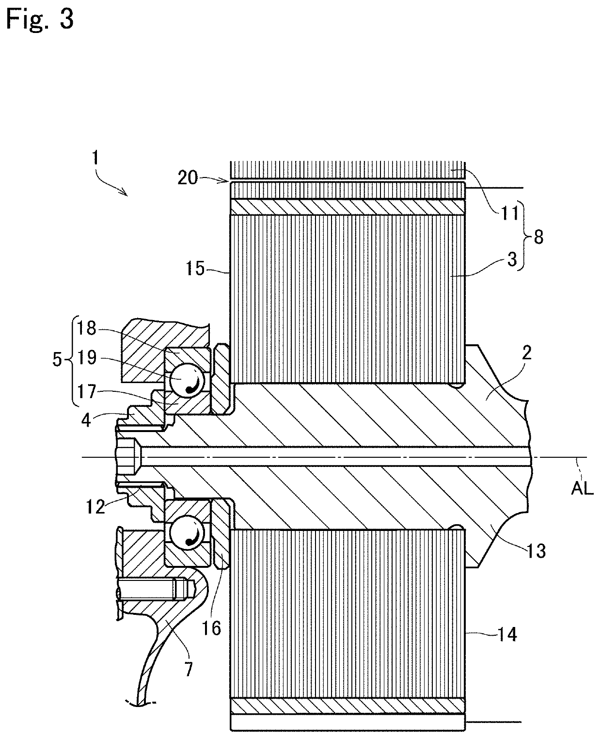
[0022]Turning now to FIG. 2, there is shown the first example of a supporting structure 1 according to the embodiment of the present disclosure. The supporting structure 1 illustrated in FIG. 2 comprises a rotor shaft 2, a rotor 3, a nut 4, a bearing 5, a bearing 6, and a case 7.

[0023]Specifically, the rotor shaft 2 is a rotary shaft of a motor 8, and a rotor 3 of the motor 8 is fitted onto the rotor shaft 2. The rotor shaft 2 may be formed integrally with another rotary shaft on which another rotary member such as a gear is mounted. According to the first example, specifically, the rotor shaft 2 is formed integrally with a gear shaft 10 on which a gear 9 is mounted.

[0024]The rotor 3 is rotated integrally with the rotor shaft 2 to serve as a rotary member of the embodiment of the present disclosure. Specifically, the motor 8 is an inner rotor type motor comprising ...


PUM


Abstract

A shaft supporting structure in which a shaft support span is reduced to prevent flexure of the shaft. In the supporting structure, a rotary member is mounted on a rotary shaft supported by bearings to be rotated integrally therewith, and the bearings are supported by a support member. The first bearing and the second bearing are disposed on both sides of the rotary member on the rotary shaft, and the first bearing is disposed between the rotary member and the fastening member in the axial direction of the rotary shaft.

Description

CROSS REFERENCE TO RELATED APPLICATIONS[0001]The present application claims the benefit of priority to Japanese Patent Application No. 2018-224410 filed on Nov. 30, 2018 with the Japanese Patent Office, the entire contents of which are incorporated herein by reference in its entirety.BACKGROUNDField of the Disclosure[0002]Embodiments of the disclosure relate to the art of a supporting structure to support a rotary shaft on which a predetermined rotary member is mounted such as a rotor shaft of a motor or a rotary shaft of a gear through a bearing.Discussion of the Related Art[0003]JP-A-2017-77148 describes a vehicular motor that can prevent an occurrence of electric corrosion of a bearing and that can reduce fuel consumption. The motor taught by JP-A-2017-77148 comprises: a hollow rotor shaft that supports an intermediate portion of a rotor core in a longitudinal direction; support members such as a main case and a rear cover that support both ends of the rotor shaft through a beari...

Claims


Application Information

Patent Timeline
IPC IPC(8): F16C19/08
CPCF16C2380/26F16C19/08H02K5/1732F16C19/54F16C35/063
Inventor SHINODA, MASASHINISHIMINE, AKIKOKATO, SHOTAROHATA, KENSEIOKITA, SO
Owner TOYOTA JIDOSHA KK
Why Eureka
Try Eureka