Snap-in valve for rubber wheels

Active Publication Date: 2017-07-11
WONDER
View PDF27 Cites 0 Cited by
  • Summary
  • Abstract
  • Description
  • Claims
  • Application Information

AI Technical Summary

Benefits of technology

[0013]Another object of the invention is to produce a

Problems solved by technology

The snap-in valves used on rubber wheels have some limits and disadvantages due above all to the material with which the valve body is made, i.e. brass.
Disadvantageously, brass is a metal that, besides being costly on the market, has a rather high specific weight and therefore makes the whole valve relatively heavy.
An increase of the weight in each single valve, albeit minimum and almost negligible in relation to the overall weight of a vehicle, nonetheless implies an increase in the consumption of fuel required for movement of the same vehicle and therefore a greater economic cost and increase in the pollution rate.
The conce

Method used


Image

  • Snap-in valve for rubber wheels
  • Snap-in valve for rubber wheels
  • Snap-in valve for rubber wheels

Examples


Embodiment Construction

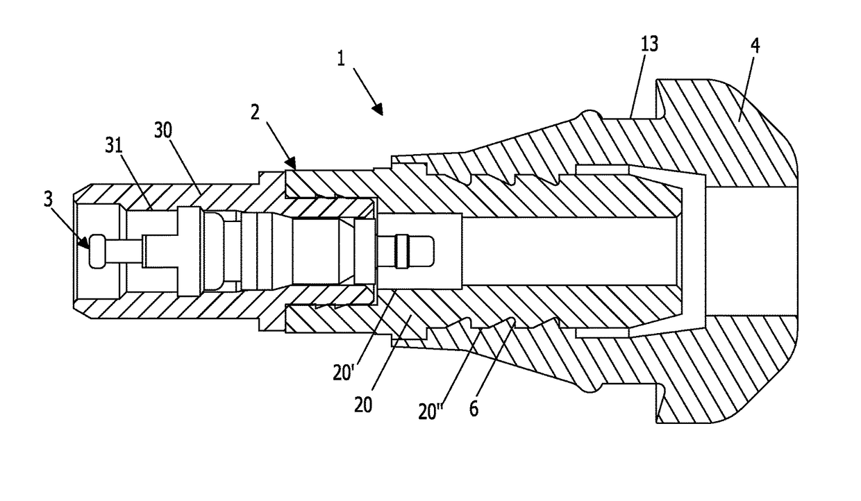
[0042]With reference to FIG. 1 there is illustrated a valve 1 of snap-in type arranged to be mounted on a rim of a rubber wheel.

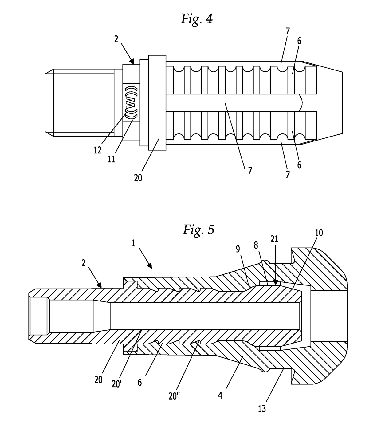
[0043]Said valve 1 substantially comprises a valve body 2, also called core, an actuating mechanism 3 arranged inside said valve body 2 and a rubber ring 4 arranged for partially covering said valve body 2.

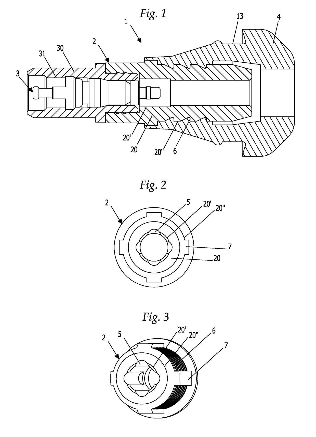
[0044]The valve body 2 has a cylindrical shape, is axially hollow and is arranged for connecting the inside of said rubber wheels with the outside environment and allowing passage of air;

[0045]In particular, said valve body 2 has a surface with external cylindrical symmetry 20″ and a surface with internal cylindrical symmetry 20′, this latter provided with a smooth portion and with a threaded portion to which said actuating mechanism 3 is screwed.

[0046]Said valve body 2 is partially covered by a rubber ring 4 that acts as seal when the valve 1 is mounted on the wheel due to cooperation between an annular groove 13 of the rubber ring 4 and a hole made in t...


PUM


Abstract

Disclosed are valves for inflating the tires of rubber wheels, in particular of vehicles, where the term vehicles is intended as motor vehicles, trucks, motorcycles or in general road transport vehicles. More in detail, the a valve (1) of snap-in type for rubber wheels includes: a hollow valve body (2) of cylindrical shape arranged for connecting the inside of the rubber wheels with the outside environment and allowing passage of air; an actuating mechanism (3) of the valve (1) arranged inside the valve body (2); a rubber ring (4), suitably shaped, arranged for partially covering the valve body (2), wherein the valve body (2) includes at least one portion (20) made of plastic material.

Description

BACKGROUND OF THE INVENTION[0001]The present invention relates to valves for inflating the tires of rubber wheels, in particular of vehicles, where the term vehicles is intended as motor vehicles, trucks, motorcycles or in general means of transport by road.[0002]More in detail, the invention relates to a valve of snap-in type, i.e. of the type that can be associated with the metal rim of the wheel by means of snap-in elastic locking means.DESCRIPTION OF THE RELATED ART[0003]These valves are generally constituted by a main body, made of a single monoblock or of several parts, of cylindrical tubular shape, acting as structural housing for an internal mechanism having the function of connecting the inside of said rubber wheels with the outside environment and of allowing, when necessary, passage of air.[0004]The valve body is hollow and provided with an axial hole, inside which there is arranged the mechanism, which can be actuated from the outside, which ensures tightness and inflati...

Claims


Application Information

Patent Timeline
IPC IPC(8): F16K15/20B60C29/02B60C29/00F16K27/02
CPCB60C29/02B60C29/005F16K15/20F16K27/02Y10T137/3584
Inventor GOSI, MATTEOCAZZANTI, STEFANOCAPELLI, ANDREA
Owner WONDER
Why Eureka
Try Eureka