

Shimming with MRI gradient
- Summary
- Abstract
- Description
- Claims
- Application Information
AI Technical Summary
Benefits of technology
Problems solved by technology
Method used
Image

Examples
Embodiment Construction
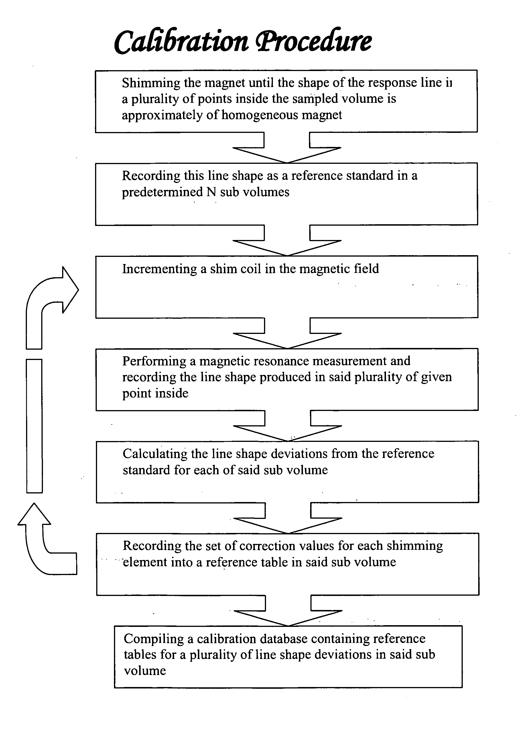
[0023] The following description is provided, alongside all chapters of the present invention, so as to enable any person skilled in the art to make use of said invention and sets forth the best modes contemplated by the inventor of carrying out this invention. Various modifications, however, will remain apparent to those skilled in the art, since the generic principles of the present invention have been defined specifically to a method of calibrating the shim coils of a magnetic resonance and to a device providing the same.
[0024] The term ‘correction value’ applies hereinafter to any parameter that effects the magnetic field around a shimming element such that the magnetic field around a sample is restored to uniformity following a disruption. Such a parameter could be the current through the coil, voltage across the coil, shape of the coil, or any other parameter.
[0025] The term ‘correction-current’ applies hereinafter to the size of the current applied to a shim coil such that ...
PUM
 Abstract
Description
Claims
Application Information