

LED driving circuit and protecting circuit thereof
- Summary
- Abstract
- Description
- Claims
- Application Information
AI Technical Summary
Benefits of technology
Problems solved by technology
Method used
Image

Examples
Embodiment Construction
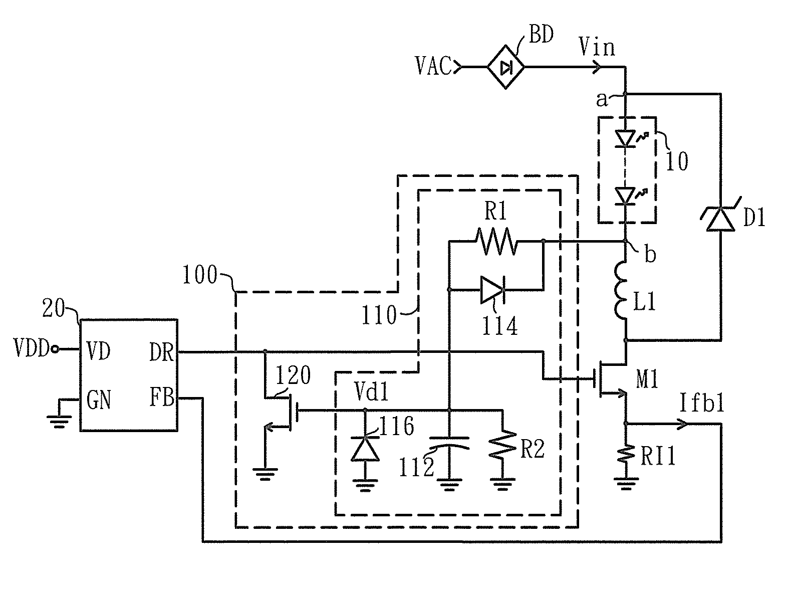
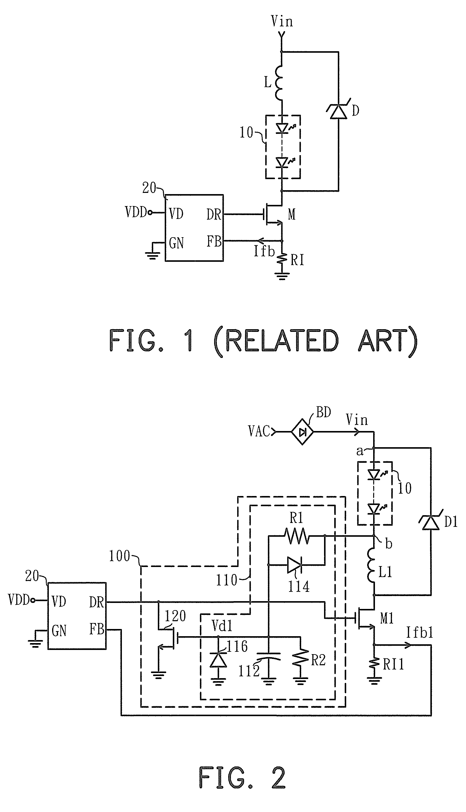
[0018]FIG. 2 is a circuit schematic diagram of a light emitting diode (LED) driving circuit according to a first exemplary embodiment of the invention. Referring to FIG. 2, the LED driving circuit includes an LED module 10, an inductor L1, a flywheel unit D1, a converting switch M1, a controller 20 and a protecting circuit 100. One end a of the LED module 10 is coupled to an alternating current (AC) power VAC, and the AC power VAC is rectified by a bridge rectifier BD to generate an input power Vin. Another end b of the LED module 10 is coupled to one end of the inductor L1, and another end of the inductor L1 is coupled to a first terminal of the converting switch M1, and a second terminal of the converting switch M1 is coupled to ground through a current detection unit RI1 and so the current detection unit RI1 generates a current feedback signal Ifb1. An anode end of the flywheel unit D1 is coupled to the first terminal of the converting switch M1, and a cathode end of the flywheel...
PUM
 Abstract
Description
Claims
Application Information