Balloon catheter

Inactive Publication Date: 2007-08-07
RANIER LIMITED
View PDF35 Cites 110 Cited by
  • Summary
  • Abstract
  • Description
  • Claims
  • Application Information

AI Technical Summary

Benefits of technology

[0025]However, a particularly preferred method of manufacture comprises forming a tubular balloon having the desired wall thickness and external diameter upon a cylindrical former or mandrel. The resultant tubular balloon is withdrawn axially from the former, which overcomes the problem of forming the former as a deflatable member. The tubular balloon is then stretched axially, for example by clamping the ends of the tube in two clamps which can be moved axially with respect to one another by an hydraulic or pneumatic ram, a screw or camming mechanism or other means. As the tube is stretched axially, its radial diameter is reduced until the internal diameter of the tube is reduced to the external diameter of the tubular portion of the catheter upon which the balloon is to be mounted. The terminal portions of the tube are then subjected to the necessary conditions, for example heat, to cause the reduced diameter of the stretched tube to become fixed. For example, the memory of the braiding can be activated so that the ends of the tube adopt the configuration at this smaller diameter to the tube. For example, the terminal

Problems solved by technology

This technique is well established, but suffers from the disadvantage that 40% of expanded constrictions spontaneously collapse within 24 months of insertion of the balloon.
Usually, such a catheter incorporates reinforcing polymer or metal fibres or braided fibres which not only provide mechanical support to the wall material of the balloon, but also restrict the extent to which the ballon can expand radially.
However, as described in WO 87/00442, problems arise with such compliant catheters in that the balloon portion moves axially within the blood vessel as the balloon portion is inflated.
Such forms of catheter are complex and expensive to manufacture and require that the various plies of the structure of the balloon portion are free to move relative to one another to accommodate the changes in geometry of the wall shape as the balloon inflates.
Furthermore, as the balloon portion is expanded radially within the blood vessel, the wall thickness reduces, weakening the balloon portion.
This thinning of the wall results in a fragile balloon portion and also results in excessive thinning, and hence localised extreme weakness, at the points where the fully inflated portion of the balloon merges into the narrow end portions by whic

Method used


Image

  • Balloon catheter
  • Balloon catheter
  • Balloon catheter

Examples


Embodiment Construction

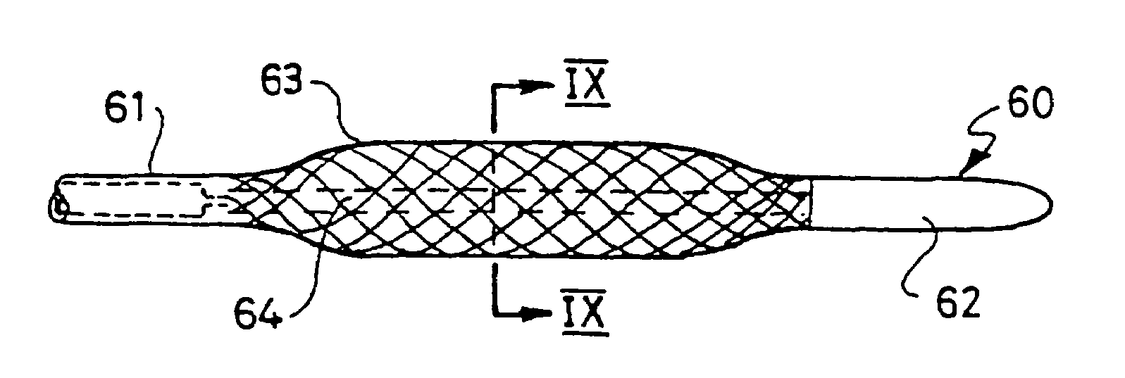
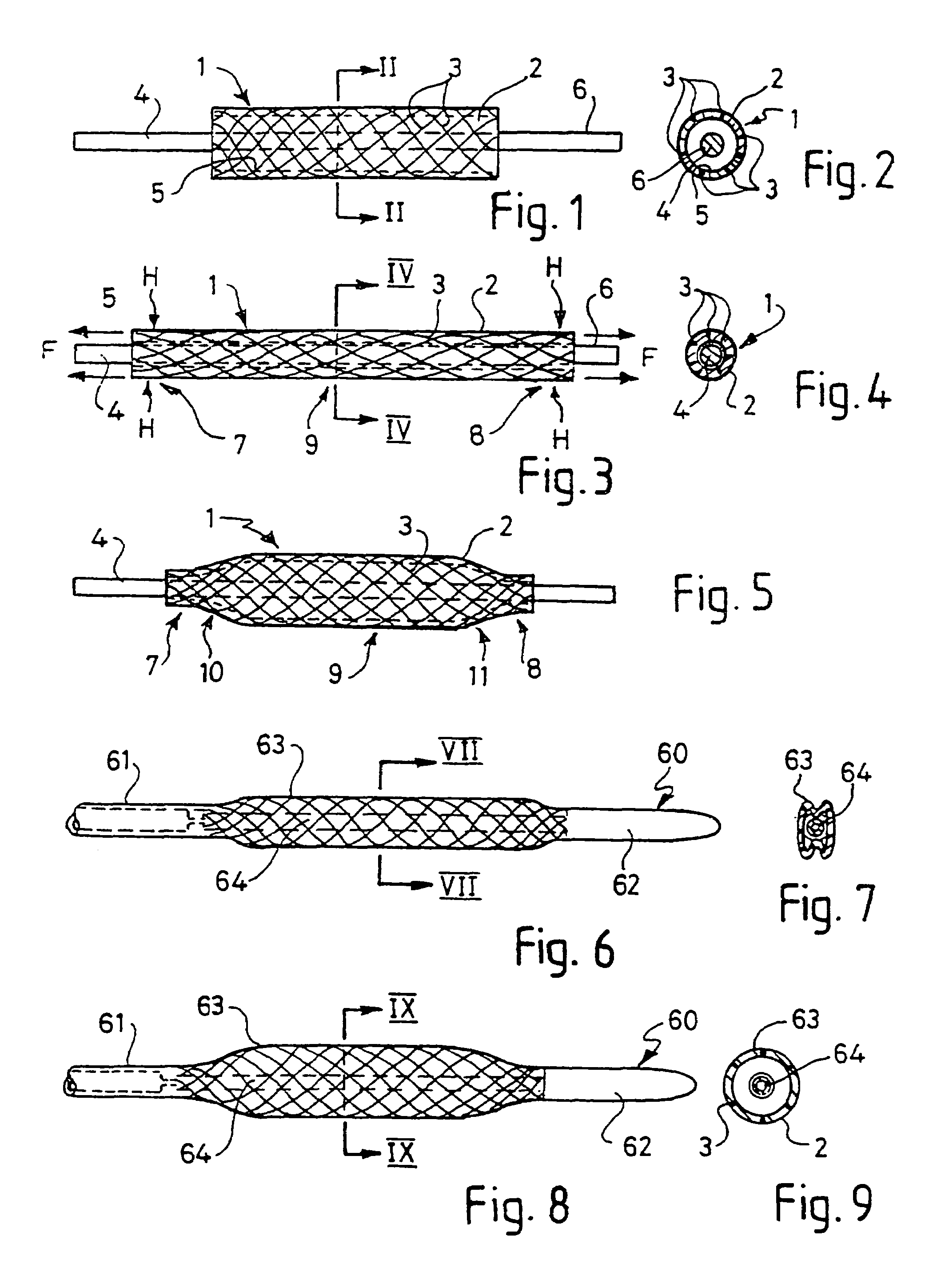
[0048]FIGS. 1 to 5 illustrate how a first embodiment of a balloon for the balloon catheter of the present invention is formed. A hollow tube 1 is formed of a flexible and resilient elastomeric material 2, in this example a polyurethane. The material 2 is reinforced with braided PET mono-filaments 3, half of which trace out right-handed parallel helixes, and the other half of which trace out left handed parallel helixes. The helixes are crossed at points, but the PET fibres are not bonded to each other at these points. The PET filaments 3 are completely surrounded by the polyurethane. The tube of this example has an outer diameter of 6 mm, an inner diameter of 5.9 mm, and a length of 25 mm. These dimensions may be larger or smaller, depending on the application for the balloon catheter. The PET fibre thickness in this example is about 40 μm, which can readily be completely contained within the wall thickness of about 100 μm for the balloon even where the fibres cross over one another...


PUM


Abstract

The present invention relates to a balloon portion for a balloon catheter for radially expanding a vessel in the body of a mammal, which catheter comprises a tube portion with a passage therethrough and a hollow expandable balloon portion defined by a fluid impervious wall and secured to the tube portion, which balloon portion can be inflated and deflated by means of a fluid passed through the passage, characterized in that:
    • a. the wall of the balloon portion is formed from a flexible substantially fluid impervious material having reinforcing fibers formed integrally with the wall material; and
    • b. the balloon portion is preformed to the desired radial diameter at its inflated state having smaller diameter end portions and a wider diameter portion intermediate the said ends and has a substantially uniform wall thickness.
The invention also provides a balloon catheter in which the balloon portion is a balloon of the invention. The invention further provides a method for making the balloon catheter of the invention.

Description

[0001]This application is a continuation of U.S. application Ser. No. 09 / 241,293, filed Feb. 1, 1999, now U.S. Pat. No. 6,156,254, the entire contents of which is hereby incorporated by reference in this application, U.S. application Ser. No. 09 / 241,293 is a continuation of PCT International Application PCT / IB97 / 00956, filed Aug. 1, 1997, which claims priority to United Kingdom application Ser. No. 9616267.2, filed Aug. 2, 1996.[0002]The present invention relates to a device, notably to a balloon catheter for locally distending a blood or other vessel in a mammal, and to a method of manufacturing a balloon for such a balloon catheter.BACKGROUND TO THE INVENTION[0003]Balloon catheters are used in surgical techniques, such as angioplasty, in which constrictions in the vascular system (usually coronary arteries) are removed by placing the balloon of the catheter at the site of the constriction and inflating the balloon by applying a gas or fluid to the ballon through the bore of the tu...

Claims


Application Information

Patent Timeline
IPC IPC(8): A61M29/00
CPCA61F2/958A61M25/0009A61M25/104A61M2025/0096A61M2025/1084
Inventor ANDREWS, GEOFFREY THOMASSNELL, ROBERT ADAM
Owner RANIER LIMITED
Why Eureka
Try Eureka