
Rod assembly for nuclear reactors

a technology for nuclear reactors and rods, which is applied in the direction of nuclear reactors, nuclear elements, greenhouse gas reduction, etc., can solve the problems of fretting damage to the component(s), generating debris of various sizes, and existence of debris of various sizes

Active Publication Date: 2007-06-14
NORDION (CANADA) INC
View PDF64 Cites 97 Cited by
  • Summary
  • Abstract
  • Description
  • Claims
  • Application Information

AI Technical Summary

Benefits of technology

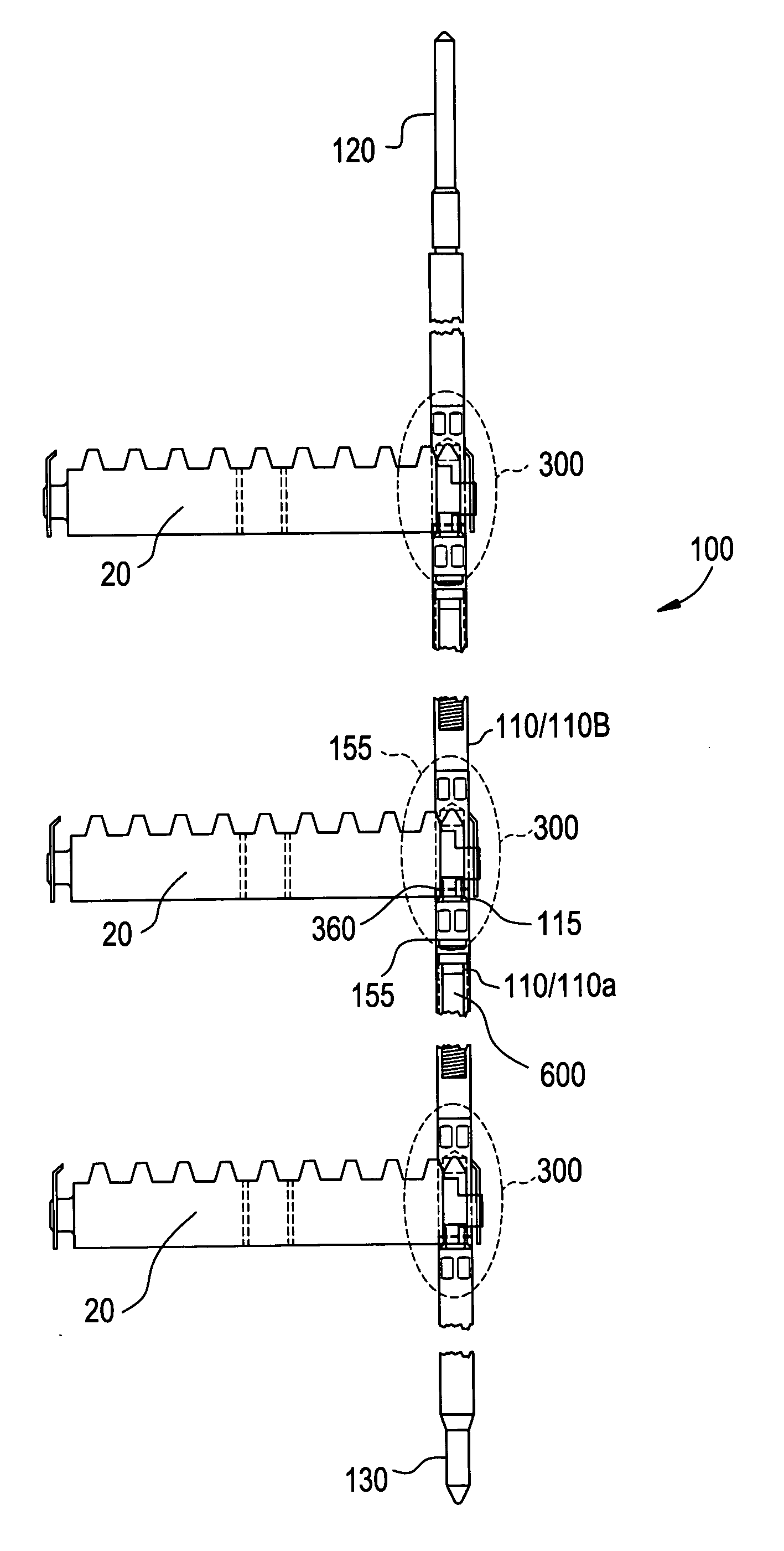
[0008] Exemplary embodiments of the present invention are directed to a rod assembly for a fuel bundle of a nuclear reactor. The rod assembly may include an upper end piece, lower end piece and a plurality of rod segments attached between the upper and lower end pieces and to each other so as to form an axial length of the rod assembly. The rod assembly may include an adaptor subassembly provided at given connection points for connecti

Problems solved by technology

A continuing problem during operation of a nuclear reactor is the existence of debris of various sizes.
The debris may be generated as a result of the original construction of the reactor core, subsequent reactor operation and / or due to repairs made during a planned or unplanned maintenance outage.
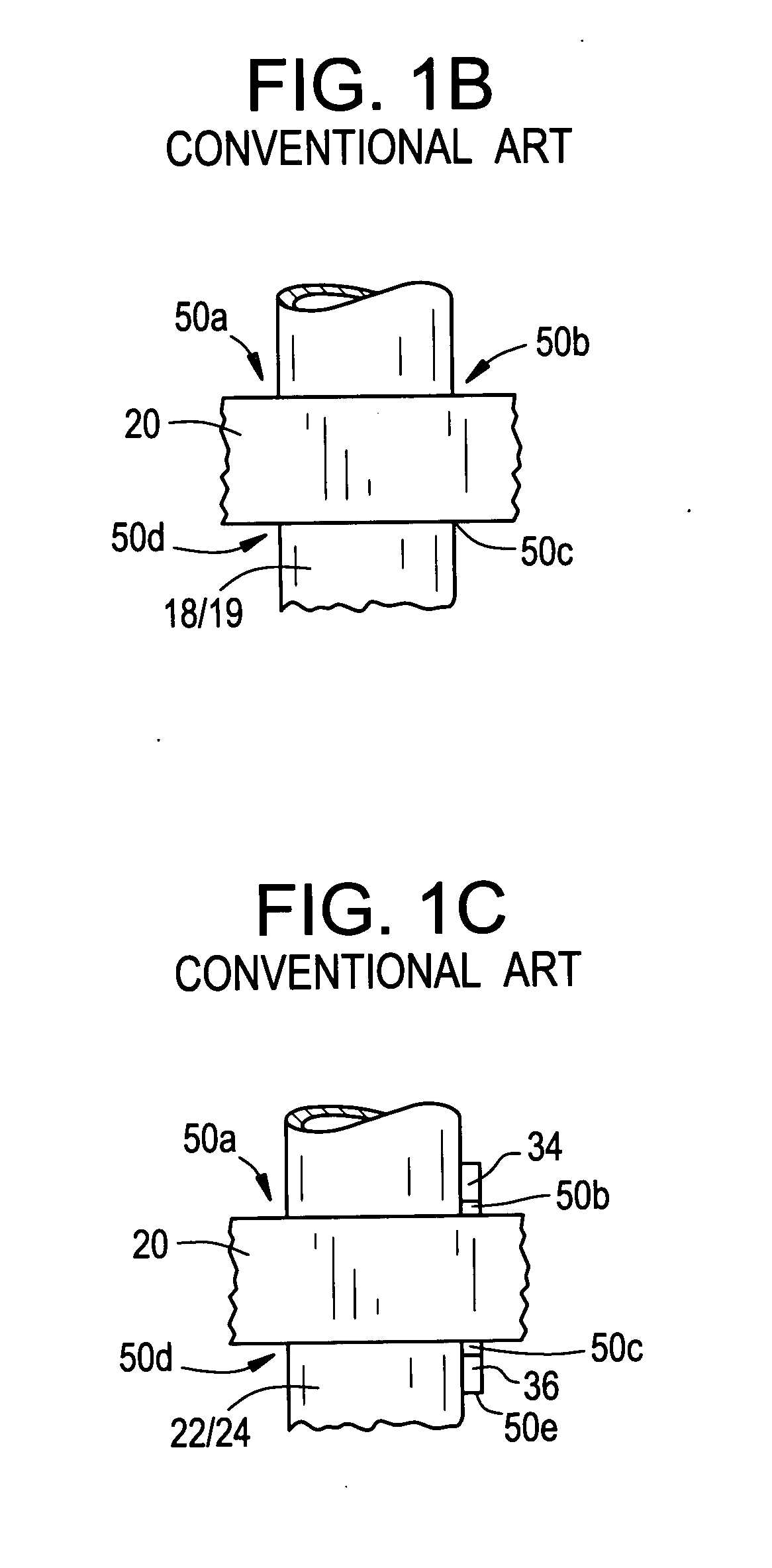
The repeated interaction between the entrained debris and component(s) can result in fretting damage to the component(s), such as damage to the fuel rods.
Some of the debris may be caught between the fuel rods and other fuel assembly components.
The debris vibrates in the moving coolant and interacts with the fuel rods, potentially causing what is known as fretting wear of the fuel rod cladding.
This fretting may be recognized as a significant cause of failure of the fuel rod in a BWR or PWR, for example.
However, the debris filter and / or external filter mechanisms do not completely obviate the fretting problem in nuclear reactors.
Fretting still may occur and cause fuel failures, which may release fuel, fission products or other rod contents into the coolant, potentially leading to the premature withdrawal from service of the fuel assembly or costly mid-cycle fuel replacement.

Method used


Image

  • Rod assembly for nuclear reactors
  • Rod assembly for nuclear reactors
  • Rod assembly for nuclear reactors

Examples


Embodiment Construction

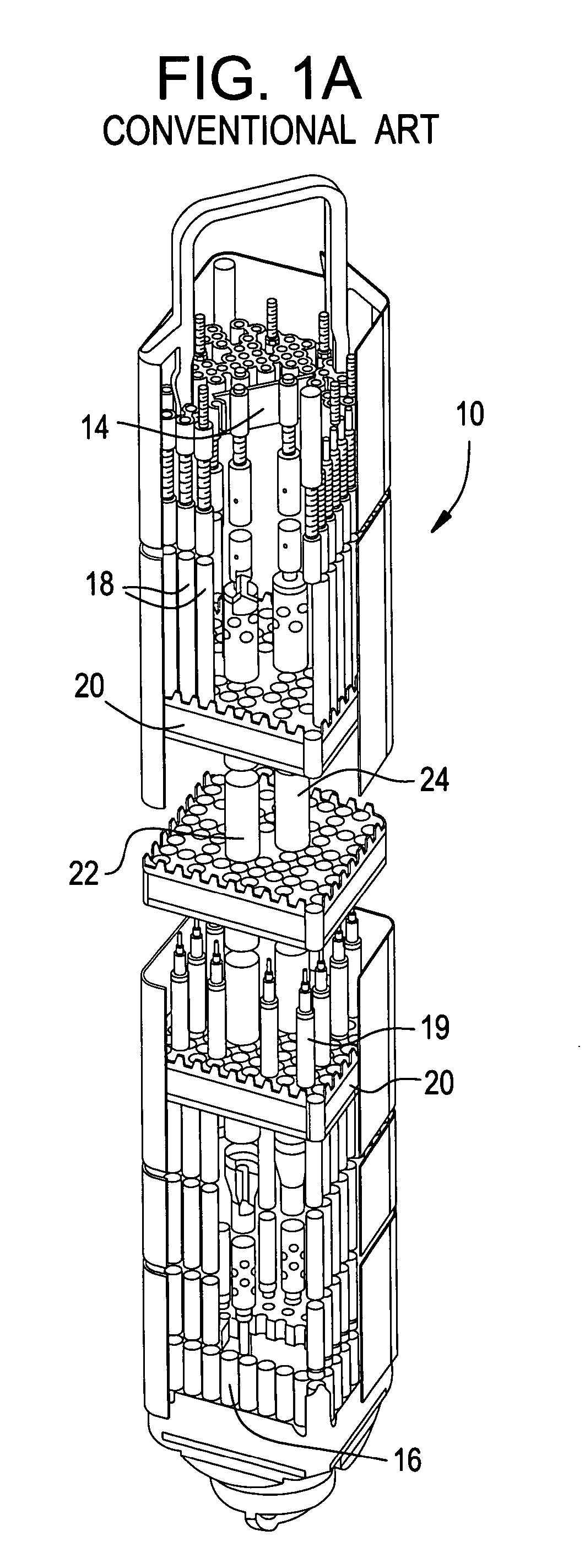
[0025]FIG. 1A illustrates an exemplary fuel bundle of a nuclear reactor such as a BWR. Fuel bundle 10 may include an outer channel 12 surrounding an upper tie plate 14 and a lower tie plate 16. A plurality of full length fuel rods 18 and / or part length fuel rods 19 may be arranged in a matrix within the fuel bundle 10 and pass through a plurality of spacers (also known as spacer grids) 20 vertically spaced one from the other maintaining the rods 18, 19 in the given matrix thereof.

[0026] The fuel rods 18 and 19 with at least a pair of water rods 22 and 24 may be maintained in spaced relation to each other in the fuel bundle 10 by a plurality of spacers 20 provided at different axial locations in the fuel bundle 10 so as to define passages for reactor coolant flow between fuel rods 18, 19 in the fuel bundle 10. There may typically be between five to eight spacers 20 spaced along the entire axial length of the fuel bundle 10 for maintaining the fuel rods 18, 19 in the desired array th...


PUM


Abstract

A rod assembly for a fuel bundle of a nuclear reactor may include an upper end piece, lower end piece and a plurality of rod segments attached between the upper and lower end pieces and to each other so as to form an axial length of the rod assembly. The rod assembly may include an adaptor subassembly provided at given connection points for connecting adjacent rod segments or a given rod segment with one of the upper and lower end pieces. The connection points along the axial length of the rod assembly may be located where the rod assembly contacts a spacer in the fuel bundle. One (or more) of the rod segments may include an irradiation target therein for producing a desired isotope when a fuel bundle containing one (or more) rod assemblies is irradiated in a core of the reactor.

Description

BACKGROUND OF THE INVENTION [0001] 1. Field of the Invention [0002] This invention relates generally to nuclear reactors, and more particularly to a rod assembly for a nuclear reactor. [0003] 2. Description of the Related Art [0004] A continuing problem during operation of a nuclear reactor is the existence of debris of various sizes. Examples of such debris may include small-sized fasteners, metal clips, welding slag, pieces of wire, etc. The debris may be generated as a result of the original construction of the reactor core, subsequent reactor operation and / or due to repairs made during a planned or unplanned maintenance outage. [0005] During the operation of such nuclear reactors, the debris may be carried by the cooling water (reactor coolant) and may become wedged between or within reactor components such as fuel rods of a fuel assembly in a boiling water reactor (BWR) or pressurized water reactor (PWR), or in control rod assemblies in a PWR, etc. The repeated interaction betw...

Claims


Application Information

Patent Timeline
IPC IPC(8): G21C3/34
CPCG21C1/303G21C3/14G21C3/326G21Y2002/303G21Y2004/303Y02E30/38Y02E30/30
Inventor FAWCETT, RUSSELL MORGANGONZALES, RANDY PETERHIGGINS, RUSSELL PATRICKJAMES, ROBERT BRYANTKIERNAN, MICHAEL THOMASRUSSELL, WILLIAM EARL IISHELTON, STEVEN BRUCESMITH, DAVID GREYSTACHOWSKI, RUSSELL EDWARDTROSMAN, LUKAS
Owner NORDION (CANADA) INC
Learn More