
Audio input-output module, plug-in detection module and methods for use therewith

Active Publication Date: 2007-06-14
TEMPO SEMICON
View PDF3 Cites 30 Cited by
  • Summary
  • Abstract
  • Description
  • Claims
  • Application Information

AI Technical Summary

Problems solved by technology

A problem common to many of these devices is that many are equipped with multiple jacks for coupling signals such as audio input / output signals to and from the device.

Method used


Image

  • Audio input-output module, plug-in detection module and methods for use therewith
  • Audio input-output module, plug-in detection module and methods for use therewith
  • Audio input-output module, plug-in detection module and methods for use therewith

Examples


Embodiment Construction

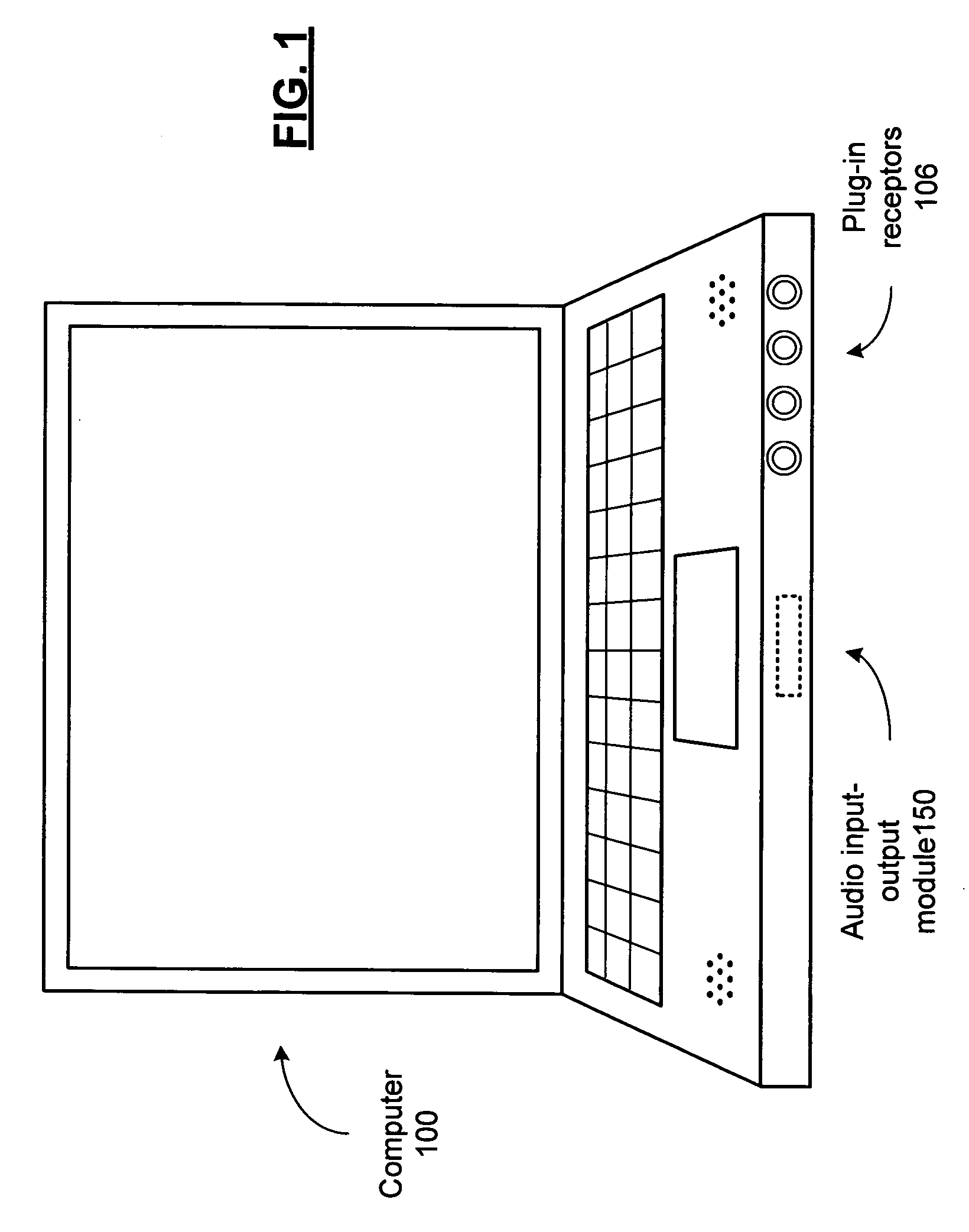
[0016]FIG. 1 presents a pictorial view of a computer in accordance with an embodiment of the present invention. In particular, computer 100 includes audio input-output module 150 for receiving audio signals, such as music, speech signals, audio tracks of movies or other signals, from an external device coupled through one or more of the plug-in receptors 106. In addition, audio input-output module is operable to provide one or more signals for coupling an audio output signal to external audio output devices such as speakers, stereo systems, headphones, ear buds, through one or more plug-in receptors 106.

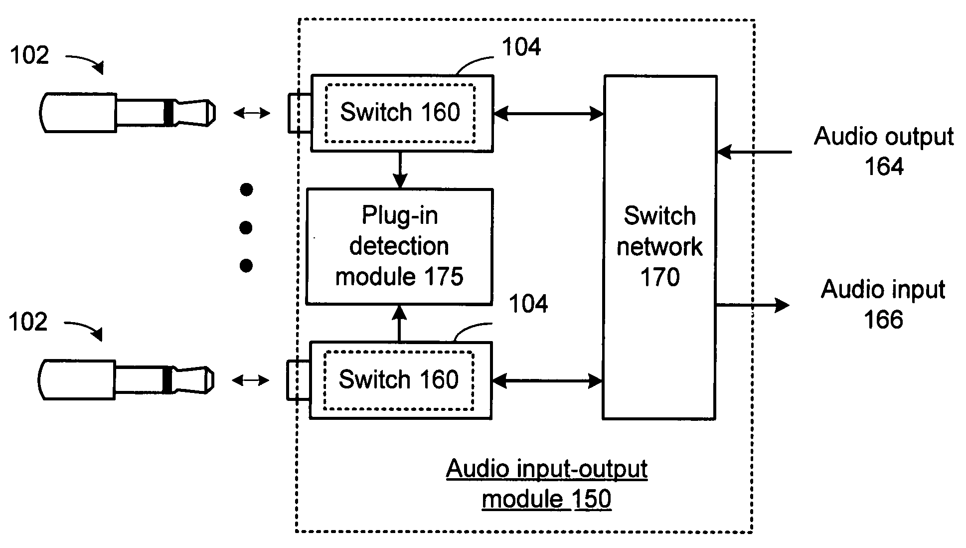
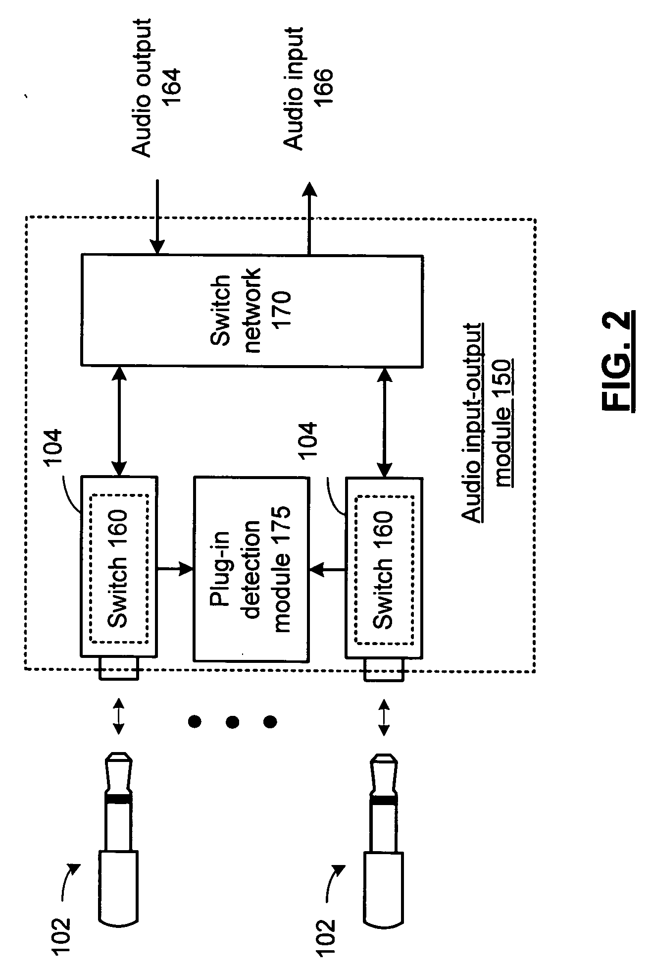
[0017] Audio input-output module 150 is capable of detecting whether or not a plug connector is coupled to each of a plurality of plug receptors including various features and functions in accordance with the present invention that will be described in conjunction with the figures that follow.

[0018]FIG. 2 presents a pictorial / block diagram representation of an audio input-output mo...


PUM


Abstract

A plug-in detection module includes an impedance network for producing a plug-in signal in response to a supply signal that varies when one of a plurality of plug-in receptors is coupled to a plug connector and when one of the plurality of plug-in receptors is decoupled. A reference signal generator generates a reference signal having a plurality of reference signal values. A comparator generates a detection signal when the plug-in signal compares favorably to the reference signal. A processing module detects which of the plurality of plug-in receptors have a plug connector coupled thereto.

Description

CROSS REFERENCE TO RELATED PATENTS [0001] None BACKGROUND OF THE INVENTION [0002] 1. Technical Field of the Invention [0003] The present invention relates to audio input-output modules as may be used in audio codecs, computers and related methods. [0004] 2. Description of Related Art [0005] As is known, audio signals are processed by a wide variety of electronic equipment, including portable, or handheld, devices. Such devices include laptop, notebook and other personal computers, personal digital assistants (PDA), CD players, MP3 players, DVD players, AM / FM radio, satellite radio systems, in-band on channel digital radios, cellular telephones, consumer audio equipment such as stereo systems, home theater systems, cable and satellite tuners and set-top boxes, digital video recorders and other systems that support the processing of audio and video, etc. Each of these devices includes one or more integrated circuits to provide the functionality of the device. As an example, a computer...

Claims


Application Information

Patent Timeline
IPC IPC(8): H02B1/00
CPCG06F3/16H01R24/58H01R29/00H01R2103/00
Inventor KANJI, AJAYKUMAR
Owner TEMPO SEMICON
Learn More