Terminal apparatus and received data display method

a technology of receiving data and terminal equipment, applied in the direction of wireless communication, instruments, broadcast service distribution, etc., can solve the problems of inability to find necessary information quickly, associated costs are a problem, etc., and achieve the effect of reducing costs

Inactive Publication Date: 2007-06-14
PANASONIC CORP
View PDF3 Cites 126 Cited by
  • Summary
  • Abstract
  • Description
  • Claims
  • Application Information

AI Technical Summary

Benefits of technology

[0011] The present invention enables costs to be reduced and necessary information to be found speedily ...

Problems solved by technology

However, with a conventional terminal apparatus and received data display method, it is necessary for distribution data to be edited for each mobile device individually on the distribution end based on the locations of mobile devices measured on the distribution end, and the associated costs are a problem.
Also, with a conventional terminal apparatus and received dat...

Method used


Image

  • Terminal apparatus and received data display method
  • Terminal apparatus and received data display method
  • Terminal apparatus and received data display method

Examples


embodiment 1

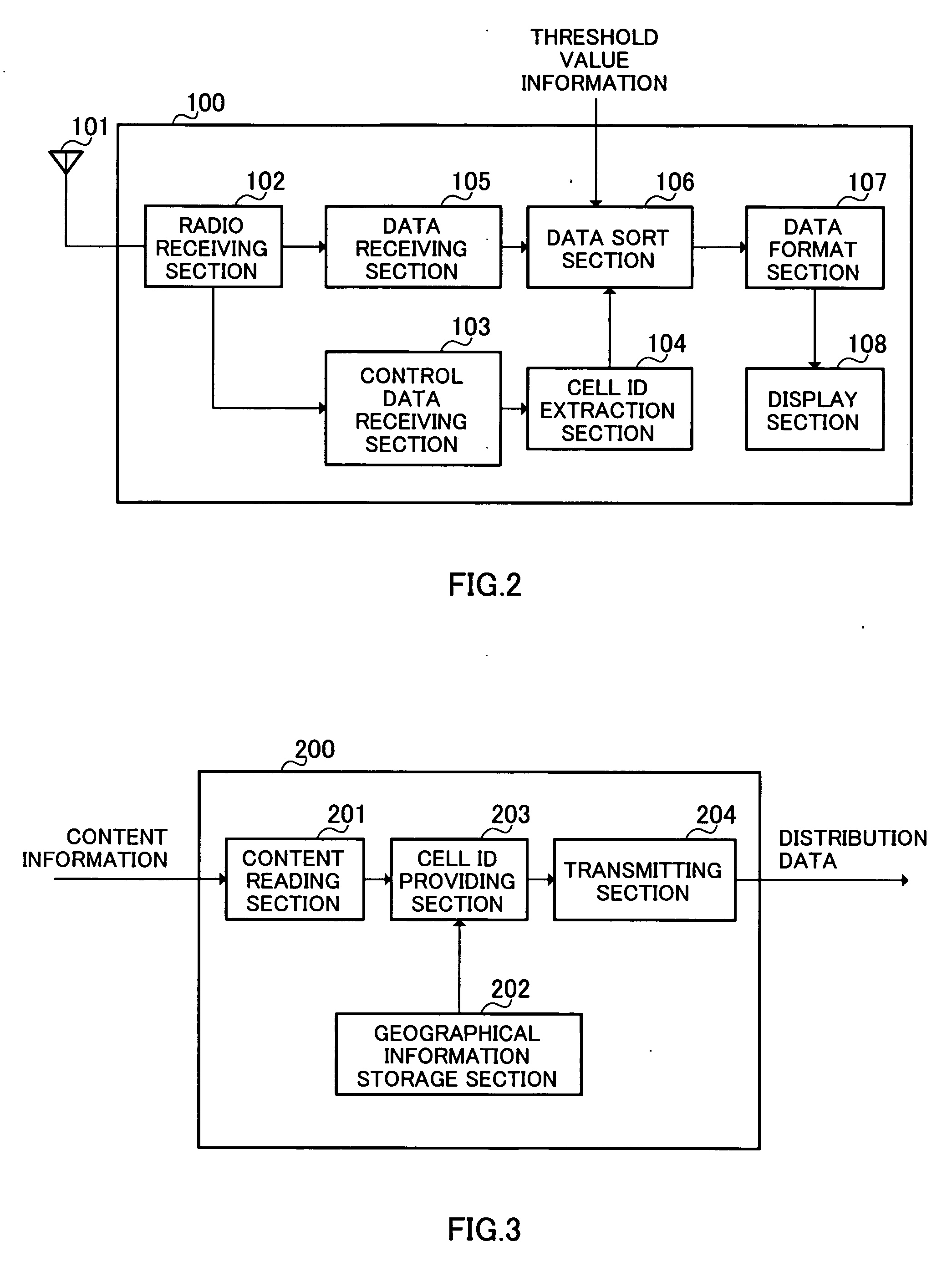
[0040]FIG. 2 is a block diagram showing the configuration of terminal apparatus 100 according to Embodiment 1 of the present invention.

[0041] Radio receiving section 102 down-converts a received signal received by antenna 101 from radio frequency to baseband frequency, and outputs the resulting signal to data receiving section 105 and control data receiving section 103.

[0042] Control data receiving section 103 extracts all control information other than application data from a received signal input from radio receiving section 102, and outputs this control information to cell ID extraction section 104.

[0043] Cell ID extraction section 104 extracts, from control information input from control data receiving section 103, the cell ID (cell information) of its own cell (hereinafter referred to as ‘the local cell’), in which terminal apparatus 100 is currently performing communication, and outputs cell ID information—that is, information as to the extracted cell ID—to data sort sectio...

embodiment 2

[0068]FIG. 12 is a block diagram showing the configuration of a terminal apparatus 1100 according to Embodiment 2 of the present invention.

[0069] Terminal apparatus 1100 according to Embodiment 2 has data sort section 1101 as shown in FIG. 12 instead of data sort section 106 in terminal apparatus 100 according to Embodiment 1 shown in FIG. 2. Parts in FIG. 12 constituting the same configuration elements as in FIG. 2 are assigned the same codes as in FIG. 2, and descriptions thereof are omitted. The configuration of a distribution server according to Embodiment 2 is identical to that in FIG. 3, and therefore a description thereof is also omitted here.

[0070] Data sort section 1101 compares the cell ID contained in distribution data with a cell ID input from cell ID extraction section 104. Then, based on the result of the comparison and the latitude and longitude at which terminal apparatus 1100 is performing communication measured using GPS or the like, data sort section 1101 arrang...

embodiment 3

[0075]FIG. 16 is a block diagram showing the configuration of a terminal apparatus 1500 according to Embodiment 3 of the present invention.

[0076] In terminal apparatus 1500 according to Embodiment 3, as shown in FIG. 16, a transmission status monitoring section 1501 and a cell ID storage section 1503 are added to the configuration of terminal apparatus 100 according to Embodiment 1 shown in FIG. 2, a cell ID extraction section 1502 is provided instead of cell ID extraction section 104, and a data sort section 1504 is provided instead of data sort section 106. Parts in FIG. 16 constituting the same configuration elements as in FIG. 2 are assigned the same codes as in FIG. 2, and descriptions thereof are omitted. The configuration of a distribution server according to Embodiment 3 is identical to that in FIG. 3, and therefore a description thereof is also omitted here.

[0077] Transmission status monitoring section 1501 measures the received signal strength of a received signal input ...


PUM


Abstract

Distributed data is not edited at a distributing end but is edited in a terminal apparatus, thereby reducing the cost. The terminal apparatus can quickly retrieve necessary information. In the apparatus, a cell ID extracting part (104) extracts all the cell IDs that can be currently received. A data receiving part (105) extracts distributed data. A data sorting part (106) compares the cell ID related to the distributed data with the cell IDs that can be currently received, and adds priorities to the distributed data in such a manner that a “high” priority is given to the distributed data related to the same cell ID as the local cell, while the lower priorities being given to the distributed data related to the cell IDs of other cells that are farther from the local cell. A display part (108) sequentially displays the distributed data in decreasing order of the priority.

Description

TECHNICAL FIELD [0001] The present invention relates to a terminal apparatus and received data display method, and relates, for example, to a terminal apparatus and received data display method used in a service whereby advertisements and suchlike distribution data are distributed to a terminal apparatus from a distribution server. BACKGROUND ART [0002] In third-generation mobile communication systems, a broadcasting service is known whereby distribution data is simultaneously transmitted to a plurality of mobile terminals (see Patent Document 1, for example). [0003]FIG. 1 is a block diagram showing the configuration of a communication system in a conventional broadcasting system in which distribution data is transmitted. FIG. 1, location information transmitting apparatus 10 is equipped with transmitting / receiving section 11, control section 12, storage section 13, and location acquisition section 14. [0004] Transmitting / receiving section 11 is used when transmitting / receiving move...

Claims


Application Information

Patent Timeline
IPC IPC(8): G07G1/14H04B7/26H04M3/487H04W4/06H04W28/00H04W64/00H04W88/02
CPCG06Q30/0241H04M3/4878H04M2201/38H04M2207/18H04M2242/06H04M2242/14H04M2242/30
Inventor IDO, DAIJIYONEMOTO, YOSHIFUMIYAMAGUCHI, TAKAOSATO, JUNICHITAKEI, ICHIRO
Owner PANASONIC CORP
Why Eureka
Try Eureka