System and method for providing reactive power support with distributed energy resource inverter

a technology of distributed energy resources and reactive power, applied in process and machine control, greenhouse gas reduction, instruments, etc., can solve the problems of increasing the cost of reactive power compensation

Active Publication Date: 2007-06-14
GENERAL ELECTRIC CO
View PDF7 Cites 78 Cited by
  • Summary
  • Abstract
  • Description
  • Claims
  • Application Information

AI Technical Summary

Problems solved by technology

For a long feeder line, voltage sag emerges as a significant issue when the reactive load is heavy.
However, this approach often requires extra capital expenditure by the utility.
Therefore, continuous coverage of the reactive power compensation can be a challenge.

Method used


Image

  • System and method for providing reactive power support with distributed energy resource inverter
  • System and method for providing reactive power support with distributed energy resource inverter
  • System and method for providing reactive power support with distributed energy resource inverter

Examples


Embodiment Construction

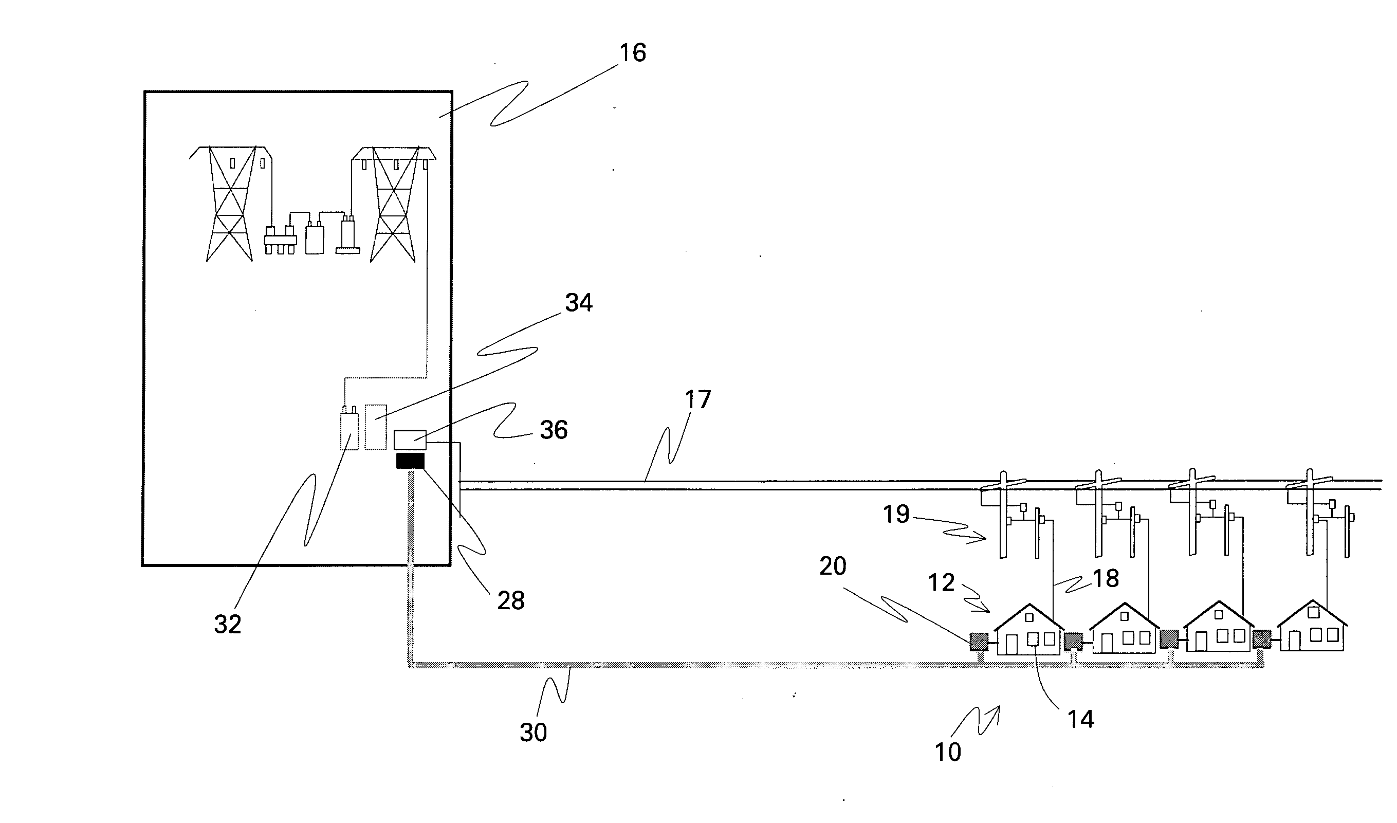
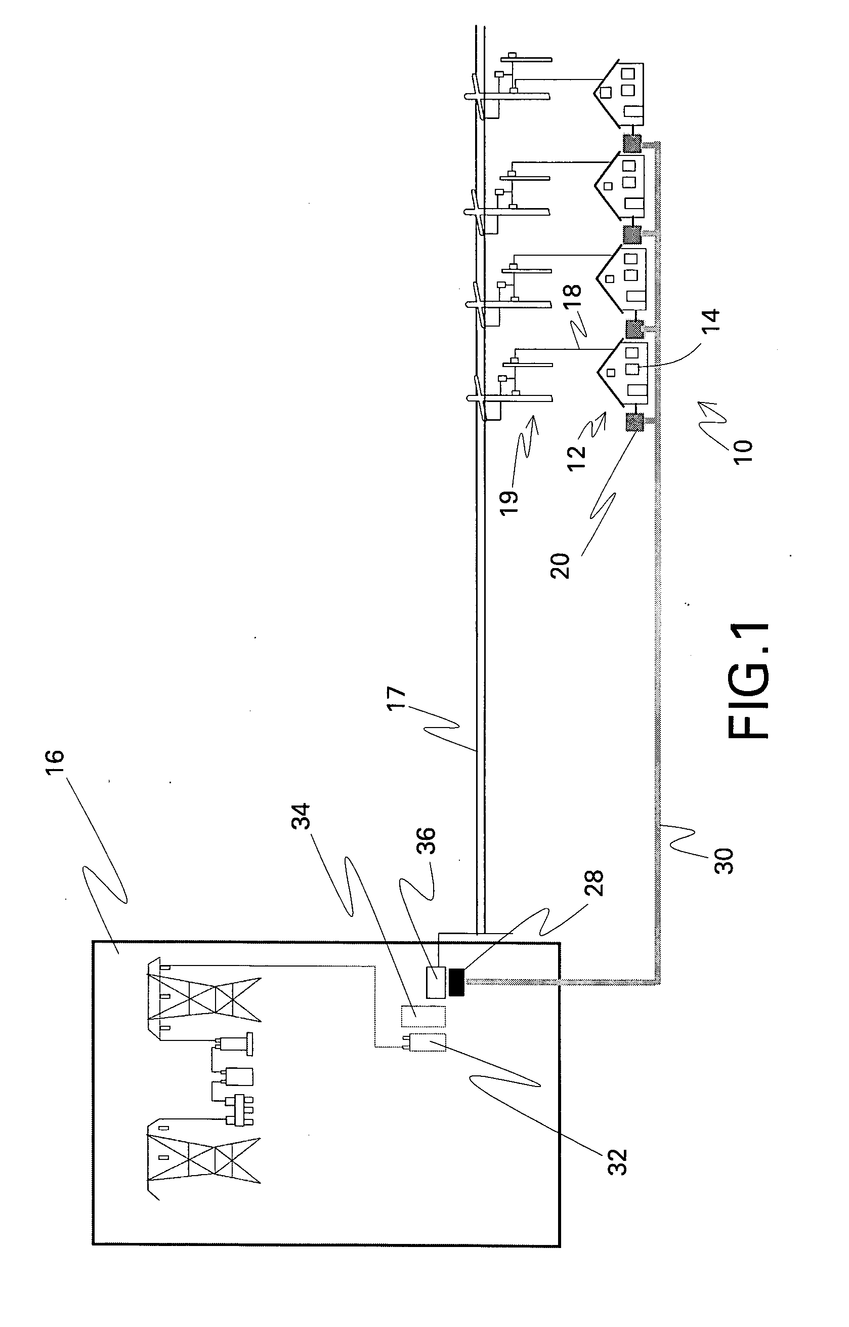
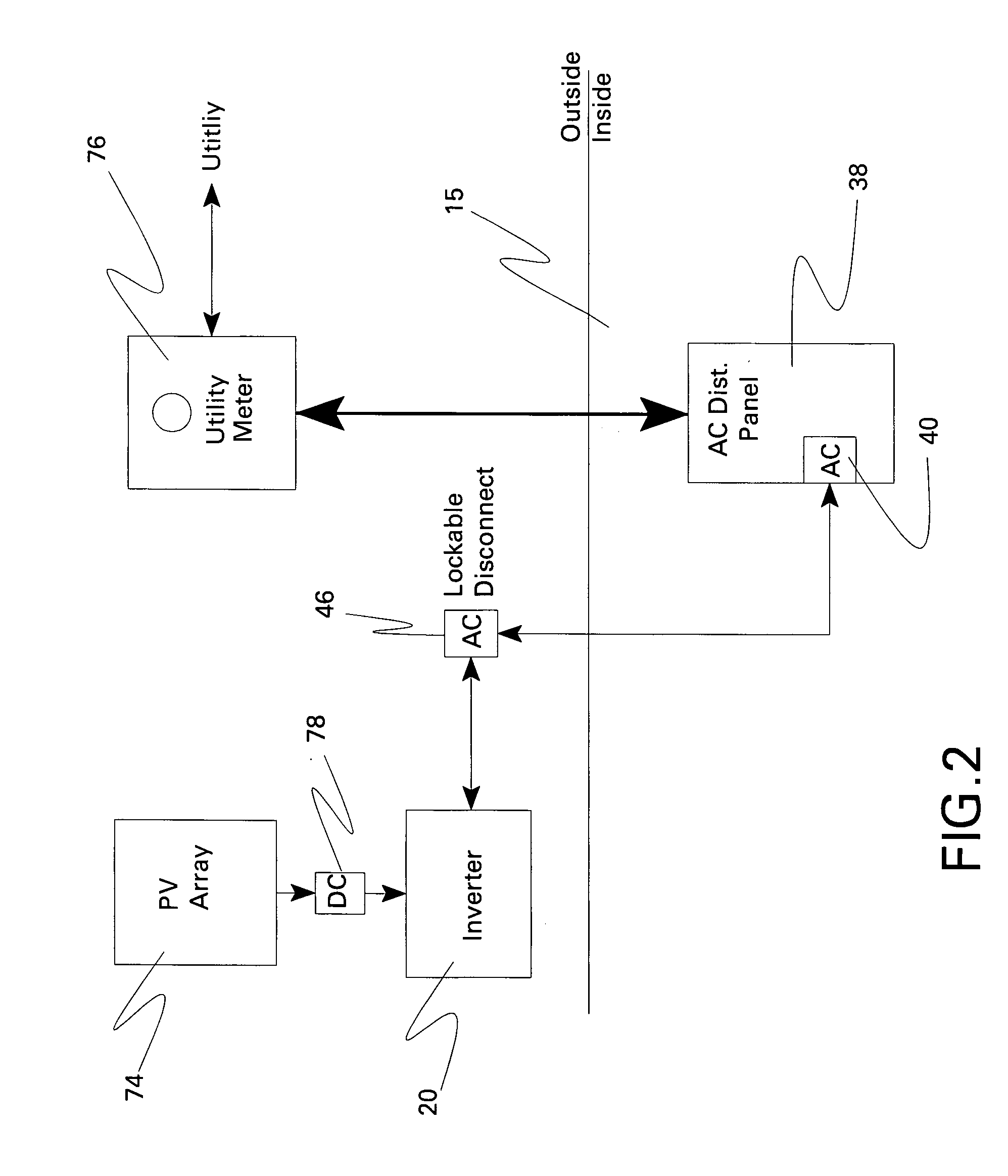
[0017]FIG. 1 is a schematic diagram of a reactive power compensation system in accordance with one embodiment of the present invention, FIGS. 2-5 are diagrams of more specific photovoltaic system embodiments, and FIG. 6 is a schematic diagram of switches between a load, a grid, and an inverter in accordance with another embodiment of the present invention. In the embodiment shown in FIGS. 1 and 6, a reactive power compensation system 10 comprises a distributed energy resource 12 situated at a local location 14 that is configured to also receive power from a remote location 16 by a distribution feeder line 18. Distributed energy resource 12 comprises an inverter 20 comprising power semiconductor switching devices 22 and an inverter controller 24 configured for controlling power semiconductor switching devices 22 so as to provide reactive power support to distribution feeder line 18.

[0018]FIG. 1 additionally illustrates an embodiment wherein remote location 16 comprises a substation ...


PUM


Abstract

A reactive power compensation system includes a distributed energy resource situated at a local location configured to also receive power from a remote location by a distribution feeder line. The distributed energy resource includes an inverter including power semiconductor switching devices and an inverter controller configured for controlling the power semiconductor switching devices so as to provide reactive power support to the distribution feeder line.

Description

BACKGROUND [0001] The invention relates generally to distributed energy resources. [0002] Electric power is delivered to residential consumers through power distribution systems that typically have radial topologies. In such power distribution systems, feeders branch out from a substation and reach a residential consumer through a step down transformer. Conventional power flow in such axial embodiments is unidirectional from the substation to the residence. [0003] In a typical radial distribution system, voltage sag (drop) along the feeder is proportional to the reactive power on the feeder according to the formula: Δ⁢ ⁢V=PR+QXV, wherein ΔV is the voltage drop, P, Q are the real and reactive power, V is the bus voltage; and R, X are feeder resistance and reactance respectively. The resistance R of the feeder line is typically orders of magnitude smaller than the reactance X. Therefore, the voltage drop on the feeder line can be depicted approximately as follows. Δ⁢ ⁢V≈QXV.[0004] F...

Claims


Application Information

Patent Timeline
Patent Type & Authority Applications(United States)
IPC IPC(8): G05D11/00H02M7/521
CPCH02J3/1835H02J3/32Y02E40/30Y02E70/30H02J3/383H02J3/386Y02E10/563Y02E10/566Y02E10/763H02J2300/28H02J2300/24H02J3/381Y02E10/56Y02E10/76
Inventor ZHOU, RUISMOLENSKI, JOSEPH LUCIANDURLING, MICHAEL RICHARDPREMERLANI, WILLIAM JAMES
Owner GENERAL ELECTRIC CO
Why Eureka
Try Eureka