Inline vaporizer

a vaporizer and inline technology, applied in the direction of burners, combustion types, breathing protection, etc., can solve the problems of reducing the energy affecting the efficiency of the humidification process, and affecting the quality of the vaporizer,

Active Publication Date: 2007-06-21
GENERICUS INC +1
View PDF33 Cites 93 Cited by
  • Summary
  • Abstract
  • Description
  • Claims
  • Application Information

AI Technical Summary

Benefits of technology

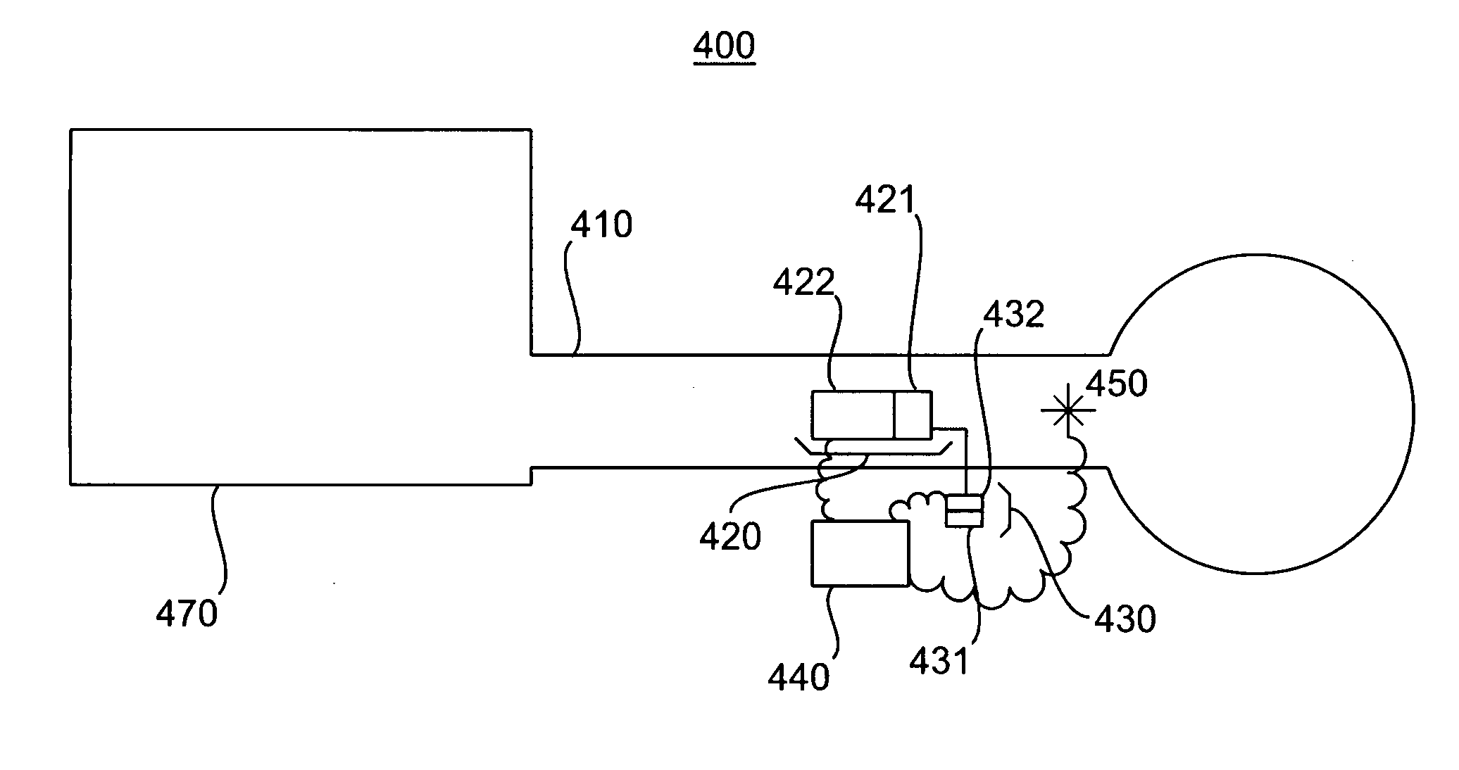
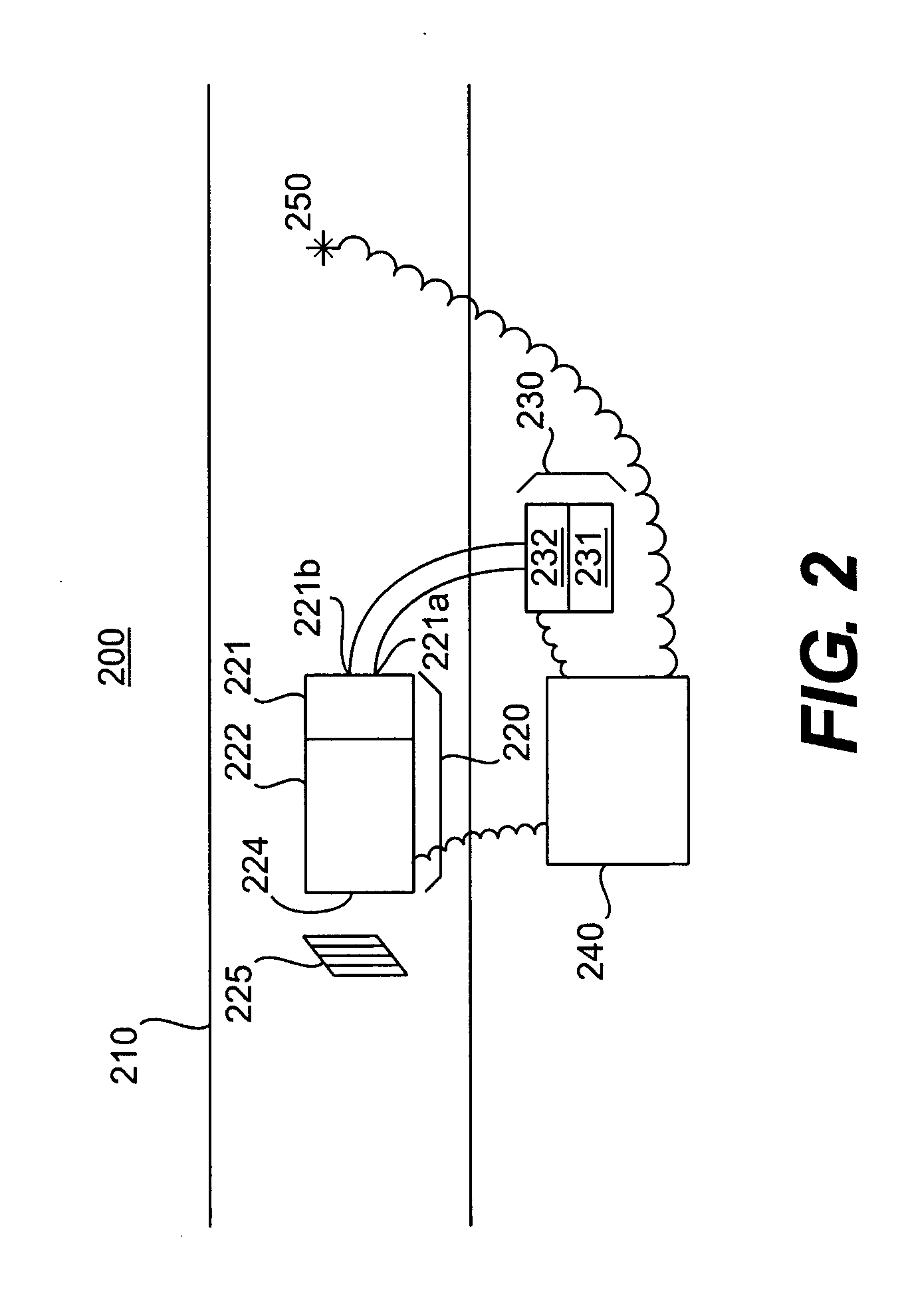
[0016] According to one embodiment of the invention, a system for adding a fluid to a carrier gas includes a carrier gas line for directing a carrier gas stream and a vaporizing device located within the carrier gas line. The vaporizing device may include a heating device having an outlet, wherein the fluid is heated to a vapor and is released at the outlet of the heating device. A carrier gas within the carrier gas line flows past the outlet of the heating device to mix and form a vapor and carrier gas mixture. The system may further include a fluid source connected to the heating device that is operable to provide the fluid to the heating device. In addition, the system may further include a carrier gas source coupled with the carrier gas line. For example, the vapor and carrier gas mixture may be delivered to a patient. The system may further include a controller, such that the heating device is responsive to the controller. The controller may include a feedback loop to control power to the heater, such that the power is adjusted faster than the thermal time constant of the heater. The fluid source may also be responsive to the controller. The system may further include a sensor located at a predetermined position along the carrier gas line, such that the controller receives a signal from the sensor. The system may further include a fluid source that is connected to the heating device and is operable to provide the fluid to the heating device, such that the fluid source is responsive to the controller based on a signal from the sensor. The heating device may also be responsive to the controller based on a signal from the sensor. The controller may control at least one of a quantity of fluid delivered to the heating device, a temperature of the heating device, and a flow rate of the carrier gas. The vaporizing device may include a porous material capillarizing the fluid and an orifice disk including at least one orifice proximate the heating device, such that the capillarized fluid passes into the at least one orifice to be vaporized by the heating device. The carrier gas line may include an air hose in fluid communication with a pump at a first end of the carrier gas line and a respiratory interface in fluid communication with the air hose and defining a second end of the carrier gas line.
[0017] In another embodiment of the invention, a system for adding a fluid to a carrier gas includes a carrier gas source operative to generate a carrier gas flow, a carrier gas line coupled to the carrier gas source at a first end of the carrier gas line such that the carrier gas line directs carrier gas flow, a fluid source having the fluid disposed therein, and a vaporizer coupled to the fluid source and disposed within the carrier gas line. The vaporizer includes an inlet that receives the fluid from the fluid source a converting element to convert the fluid and an outlet through which the converted fluid enters the carrier gas line to mix with the carrier gas. The system also includes a second end of the carrier gas line downstream from the vaporizer, such that the carrier gas flow includes a mixture of the carrier gas and the converted fluid. The system may further include a controller coupled to the fluid source that is operative to control the concentration of the converted fluid in the carrier gas flow downstream from the vaporizer. The carrier gas line may include an air hose in fluid communication with the pump at the first end of the carrier gas line and a patient respiratory interface in fluid communication with the carrier gas source at the second end of the carrier gas line. The vaporizer may be disposed proximate a connection between the air hose and the respiratory interface. The vaporizer may also disposed proximate a junction between the air hose and the respiratory interface. The respiratory interface may be a mask, for example. The converting element may be a heating element. The vaporizer inlet may include a porous material capillarizing the fluid and an orifice disk including at least one orifice proximate the converting element, such that the capillarized fluid passes into the at least one orifice to be converted by the converting element. The controller may be operative to control at least one characteristic of the mixture of the carrier gas and the vaporized fluid. The controller may include a sensor that senses at least one of a quantity of fluid delivered to the converting element and a temperature of the heating element. The controller controls at least one of the quantity of fluid delivered to the converting element, the temperature of the heating element, and a flow rate of the carrier gas. The converting element may include a nebulizer.

Problems solved by technology

These systems are an alternative to conventional ventilators and / or humidifiers that provide only dry air, which may damage the respiratory tissues.
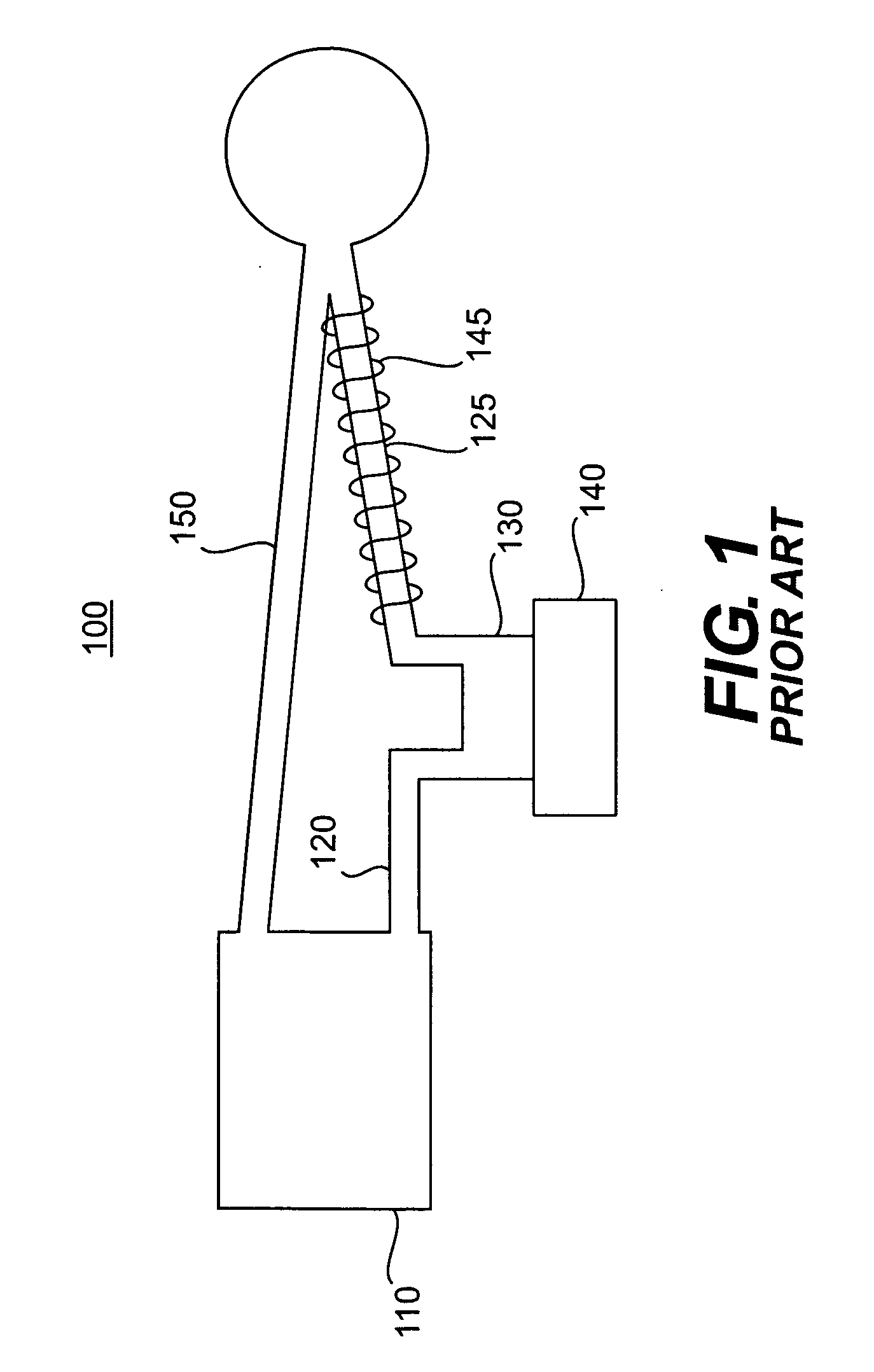
One of the disadvantages of the above-described conventional ventilator humidifier system 100 is that the addition of a second heater 145 along the second feed line 125 requires additional energy, which reduces the energy efficiency of the humidification process.
This prolonged start-up time delays the operation of the system 100, and may require a health care provider to expend additional time when treating a patient.
In addition, with this configuration, it is difficult to measure or adjust the amount of humidity in the system.
Further, the addition of a heating coil 145 along the second feed line 125 may complicate the operation of the system 100 and render it unwieldy because the bulky heating coil 145 must be positioned near the patient.
The heater 140 also poses a risk of injury, such as bums, because it is positioned outside the first feed line.
The external positioning of the heater 140 with respect to the first feed line 120 also results in heat loss to ambient air, which reduces the overall efficiency of the conventional ventilator humidifier system 100.

Method used


Image

  • Inline vaporizer
  • Inline vaporizer
  • Inline vaporizer

Examples


Embodiment Construction

[0040] The embodiments of the invention and the various features and advantageous details thereof are explained more fully with reference to the non-limiting embodiments and examples that are described and / or illustrated in the accompanying drawings and detailed in the following description. It should be noted that the features illustrated in the drawings are not necessarily drawn to scale, and features of one embodiment may be employed with other embodiments as the skilled artisan would recognize, even if not explicitly stated herein. Descriptions of well-known components and processing techniques may be omitted so as to not unnecessarily obscure the embodiments of the invention. The examples used herein are intended merely to facilitate an understanding of ways in which the invention may be practiced and to further enable those of skill in the art to practice the embodiments of the invention. Accordingly, the examples and embodiments herein should not be construed as limiting the ...


PUM


Abstract

An inline vaporizer disposed in a carrier gas line vaporizes a fluid and adds such vaporized fluid to a carrier gas that flows within the carrier gas line. The vaporizer includes a reservoir or wick that transfers a fluid to a vaporizing element that is adjacent to the reservoir or wick. The vaporizer releases a vapor into the carrier gas line so that the carrier gas flows past the vaporizer to form a vapor and carrier gas mixture.

Description

CROSS-REFERENCE TO RELATED APPLICATION [0001] This application claims priority under 35 U.S.C. §119(e) to U.S. Provisional Patent Application No. 60 / 741,047, filed on Dec. 1, 2005, the disclosure of which is expressly incorporated by reference herein in its entirety.BACKGROUND OF THE INVENTION [0002] 1. Field of the Invention [0003] The invention relates to an inline vaporizer, and more particularly to an inline vaporizer disposed within a gas line for mixing a substance such as water into a carrier gas flow. [0004] 2. Related Art [0005] Various types of systems have been developed for combining a gas such as air with a vaporized fluid for use in such applications as ventilator humidifiers, drug delivery systems (nebulizer), and combustion apparati creating fuel / gas vaporized mixture (stove burner, fuel injector). [0006] Ventilator humidification systems have been developed to create a mixture of air and water vapor to provide a patient a more comfortable intake of oxygen through th...

Claims


Application Information

Patent Timeline
Patent Type & Authority Applications(United States)
IPC IPC(8): A61M16/00A62B7/00
CPCA61M16/16A61M16/161A62B9/003A61M2205/3368A61M16/026
Inventor WEINSTEIN, LAWRENCE ALANTIFFIN, NORMAN HUGHTRAN, TUAN QUOCSUNSTEIN, DREW E.CURRIE, DOUGLAS H. JR.ROCHE, DAVID E.
Owner GENERICUS INC
Why Eureka
Try Eureka