
Method for Insert Molding Bendable Position-Retaining Tubing

a technology of bendable position and tubing, which is applied in the direction of pipes, manufacturing tools, mechanical equipment, etc., can solve the problems of no effective processing combination, and achieve the effect of preventing liquid contamination and minimizing corrosion or degradation

Inactive Publication Date: 2007-06-21
MERCURY PLASTICS LLC
View PDF16 Cites 73 Cited by
  • Summary
  • Abstract
  • Description
  • Claims
  • Application Information

AI Technical Summary

Benefits of technology

[0023] It is another object of this invention to illustrate a process that allows for at least partial insertion of two or more position retaining means, preferably wires, in different locations axially adjacent to the perimeter of the hollow tube, made preferably by extrusion, as well as in different special relationships along the longitudinal axis of the hollow tube to allow the tubing to retain a manually formed position without relaxing to its original essentially linear position when the position forming pressure is removed.
[0025] It is another object of this invention to illustrate a process for the manufacturing of a flexible, non-linear position-retaining tubing that allows the liquid or gas to flow without contact with the typically metallic insert wire that allows the tubing to retain its non-linear shape, minimizing corrosion or degradation of the typically metallic insert as well as preventing contamination of the liquid or gas flowing through the tubing.

Problems solved by technology

To date there has been no effective processing combination which combines the speed of extrusion with injection molding to fabricate fluid or gas transporting conduits which retain a non-linear shape upon the application of an external force which imparts a bend into the longitudinal axis of the part.

Method used


Image

  • Method for Insert Molding Bendable Position-Retaining Tubing
  • Method for Insert Molding Bendable Position-Retaining Tubing
  • Method for Insert Molding Bendable Position-Retaining Tubing

Examples


Embodiment Construction

[0052] Referring now to the drawings wherein the showings are for purposes of illustrating numerous embodiments of the invention only and not for purposes of limiting the same, the figures show tubing that is bendable and able to retain a manually induced position

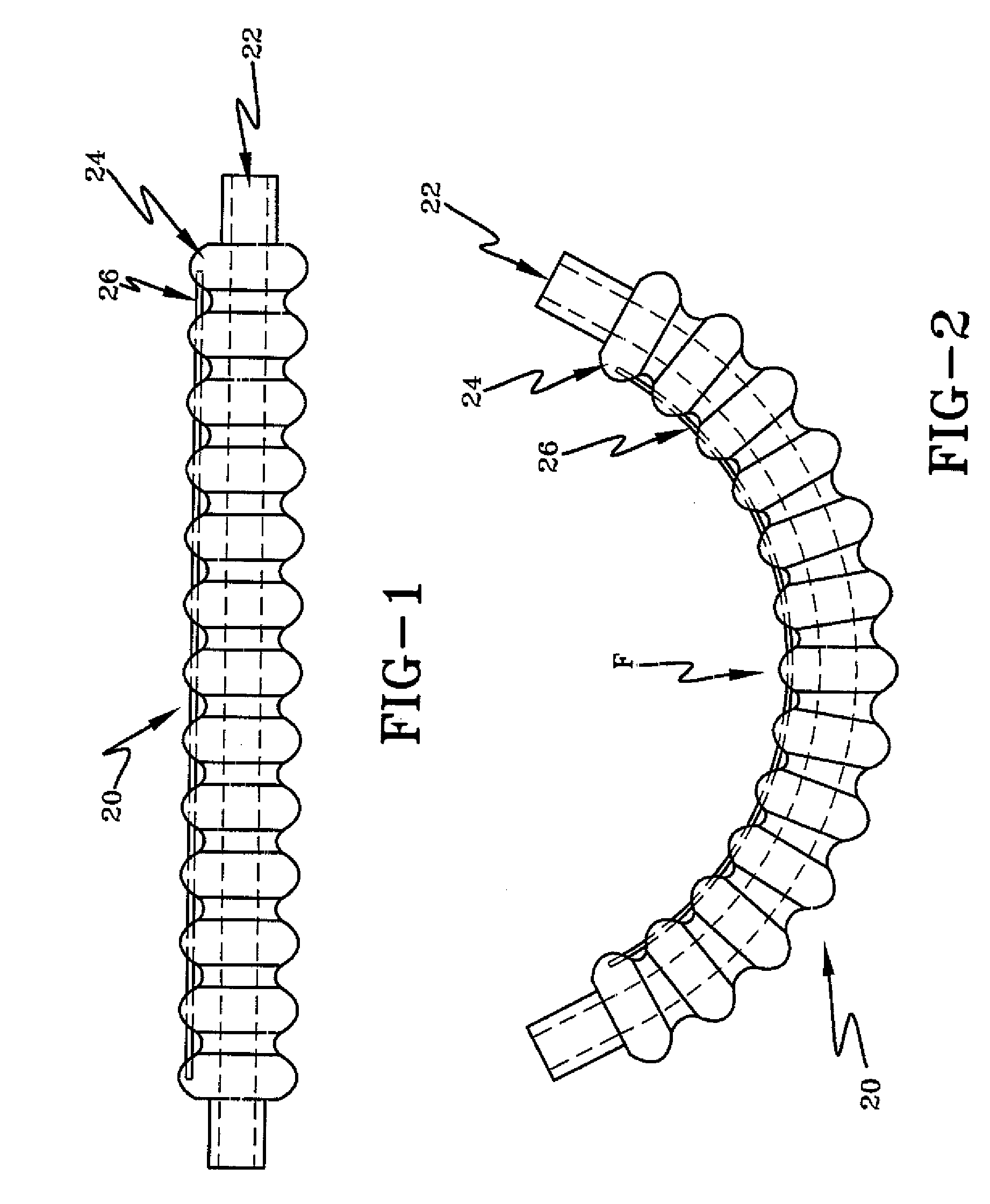
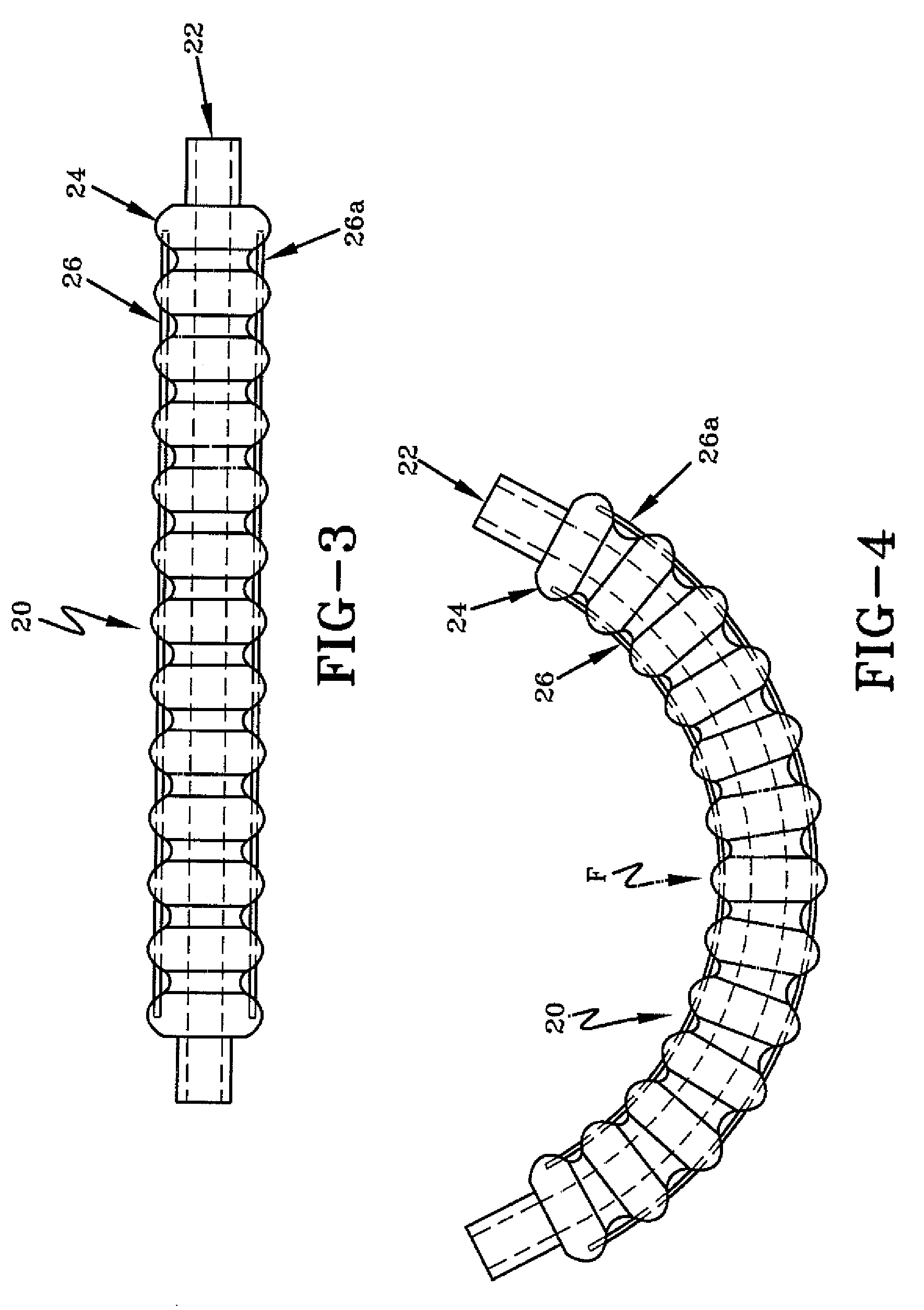
[0053]FIGS. 1-2 illustrate an embodiment of the invention. FIG. 1 illustrates the tubing 20 in its original, essentially linear, position before an external bending force has been applied. The inner essentially linear and cylindrical conduit 22 made of the first polymer, preferably by extrusion, is attached to the overmolded second polymer 24 which creates the corrugated external wall of the final tubing product 20. While the external wall illustrated in FIG. 1 is corrugated, the invention is not limited to that geometer. Other shapes and textures are within the scope of the invention or its equivalents. Flexible wire 26 is at least partially embedded or inserted into the second overmolded injected polymer 24, giving the f...


PUM

PropertyMeasurementUnit
Timeaaaaaaaaaa
Lengthaaaaaaaaaa
Flexibilityaaaaaaaaaa

Abstract

A hollow conduit, being primarily round, or having n sides wherein n is greater than or equal to three, and process for making the conduit is described herein. The hollow conduit is comprised of a polymer inner conduit having a pair of opposed ends and an interior and exterior surface. An overmolded corrugated polymer is bonded between at least a portion of the ends and at least a portion of the exterior surface of the inner conduit. The overmolded polymer has at least one flexible position retaining means at least partially embedded within. The flexible position retaining means within the overmolded polymer may be a metallic wire. The inner conduit may be a thermoset, and the overmolded corrugated plastic may be a thermoplastic.

Description

Cross-Reference [0001] This application claims priority from Provisional Patent Application Ser. No. 60 / 597,667 filed Dec. 16, 2005.TECHNICAL FIELD [0002] The invention relates generally to bendable position-retaining and / or repositionable yet shape-retaining tubing. In one embodiment of the invention at least one second polymer having at least one position retaining means at least partially embedded therein is molded onto a conduit made of a first polymer. More particularly, the invention relates to the processing of a conduit made of a first polymer, such processing involving injection overmolding of another typically thermoplastic material with flexible wire at least partially embedded therein to form flexible, position-retaining as well as repositionable yet shape retaining tubing. BACKGROUND OF THE INVENTION [0003] Thermoplastic tubing is used in a variety of applications, such as appliance input and output lines, garden hoses, automobile hoses, medical devices, etc. The tubing...

Claims


Application Information

Patent Timeline
IPC IPC(8): F16L11/00
CPCF16L11/08F16L11/112F16L11/115
Inventor RUSHLANDER, GRANDINSEMAN, RICHARD T.
Owner MERCURY PLASTICS LLC
Learn More