Regulator bypass switch assembly

a technology of bypass switch and regulator, which is applied in the direction of hot stick switch, contact mechanism, contact, etc., can solve the problems of increasing the amount of time needed to isolate or connect the regulator, and the operator providing maintenance to the regulator, if the regulator is not isolated from the system, the risk of not being able to provide the operator with the regulator's maintenance is high

Active Publication Date: 2007-06-21
HUBBELL INC
View PDF19 Cites 5 Cited by
  • Summary
  • Abstract
  • Description
  • Claims
  • Application Information

AI Technical Summary

Benefits of technology

[0008] Accordingly, it is an objective of the present invention to provide a regulator bypass switch assembly in which a single operation moves all the blades of the switch assembly to either isolate or connect the regulator from or to the electrical distribution system, thereby eliminating the risk of inadvertently forgetting to move a blade to its correct position by the operator.
[0009] Accordingly, another objective of the present invention is to provide a regulator bypass switch assembly that substantially eliminates residual current between the load side disconnect blade and its mating contact.

Problems solved by technology

Requiring multiple operations to open and close various blades is inefficient and increases the amount of time needed to isolate or connect the regulator.
Moreover, multiple blade operations may result in an operator inadvertently forgetting to open or close one of the blades, thereby not isolating or connecting the regulator from or to the electrical system or not maintaining a continuous supply of electrical power.
While not maintaining a continuous supply of electrical power is inconvenient to those relying on the supply of electrical power, not isolating the regulator from the system could be highly dangerous to the operator providing maintenance to the regulator.

Method used


Image

  • Regulator bypass switch assembly
  • Regulator bypass switch assembly
  • Regulator bypass switch assembly

Examples


Embodiment Construction

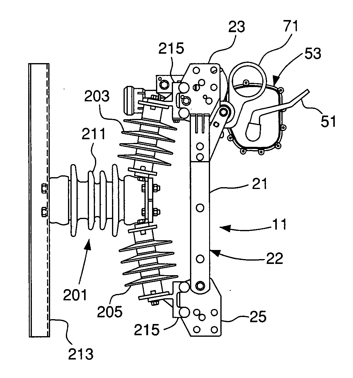
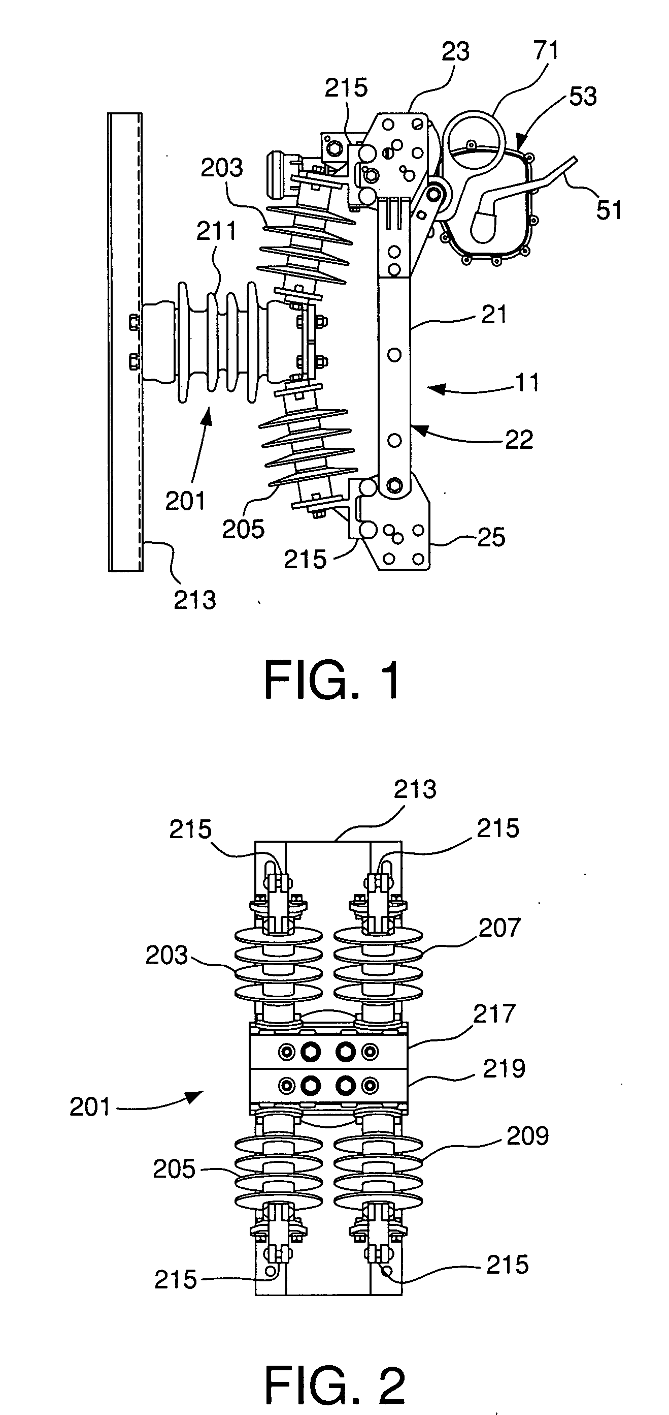
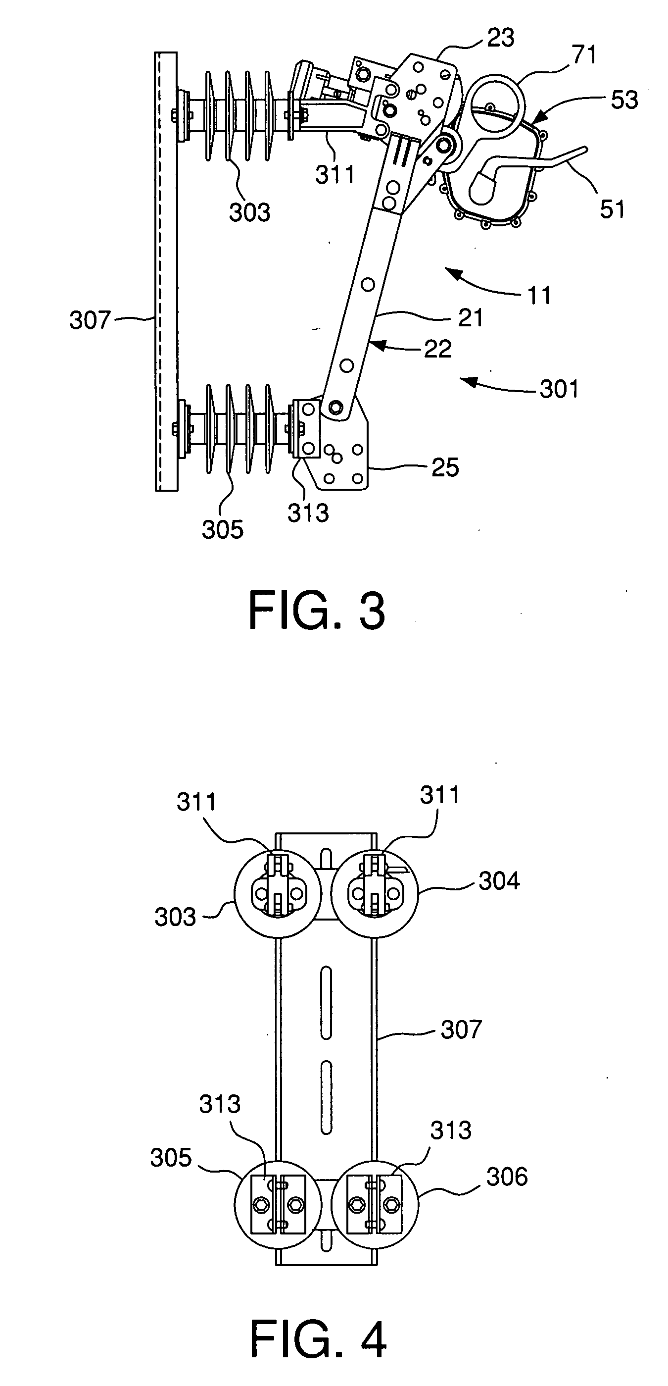
[0042] As shown in FIGS. 1 and 3, the present invention relates to station and distribution class regulator bypass switch assemblies, respectively. As shown in FIGS. 2 and 4, the present invention relates to the base, insulators and current carrying parts mounting adapters relative to station and distribution class switch assemblies, respectively. FIGS. 1 and 2 show a station class bypass switch assembly 201. FIGS. 3 and 4 show a distribution class bypass switch assembly 301. FIGS. 5-39 relate to both the station and distribution class bypass switch assemblies.

[0043]FIGS. 1-2 show a regulator bypass switch assembly 11 according to an exemplary embodiment of the present invention being used with a station class system 201. FIGS. 3-4 show the regulator bypass switch assembly 11 being used with a distribution class system 301 according to another exemplary embodiment of the present invention. The regulator bypass switch assemblies 11 used with the distribution and substation systems a...


PUM

PropertyMeasurementUnit
breakingaaaaaaaaaa
residualaaaaaaaaaa
electricalaaaaaaaaaa

Abstract

A bypass blade is pivotably connected to the first terminal pad, and movable between open and closed positions. The bypass blade is electrically connected between the first and third terminal pads when in the closed position. A first disconnect blade is pivotally connected to a second terminal pad and movable between open and closed positions. The first disconnect blade is electrically connected between the first and second terminal pads when in the closed position. A second disconnect blade is pivotally connected to a fourth terminal pad and movable between open and closed positions. The second disconnect blade is electrically connected between the third and fourth terminal pads when in the closed position. An interrupter lever is connected to an interrupter and electrically connected to the third terminal pad. A hook ring is connected to the first and second disconnect blades. The hook ring is movable between closed and open positions. Moving the hook ring from the closed position to the open position moves the first and second disconnect blades from the closed position to the open position, moves the bypass blade from the open position to the closed position and moves the interrupter lever to trip the interrupter internally to break a residual current path between the second disconnect blade and the third terminal pad.

Description

CROSS REFERENCE TO RELATED APPLICATION [0001] This is a divisional of U.S. patent application Ser. No. 11 / 297,806, filed Dec. 9, 2005.FIELD OF THE INVENTION [0002] The present invention relates to a regulator bypass switch assembly. More particularly, the present invention relates to a regulator bypass switch assembly in which a single pull or push operates the switch blades in proper sequence. Still more particularly, the present invention relates to a substation or distribution class system having a regulator bypass switch assembly in which a single pull or push operates the switch blades in proper sequence to isolate the regulator from or connect the regulator to the circuit. BACKGROUND OF THE INVENTION [0003] Regulators mounted to support structures and electrically connected to electrical power distribution systems regulate voltage in the system to prevent overvoltage and undervoltage conditions despite varying load conditions. Regulators may also be used to control voltage dur...

Claims


Application Information

Patent Timeline
Patent Type & Authority Applications(United States)
IPC IPC(8): H01H31/28
CPCH01H31/006H01H31/10Y10T29/49195Y10T29/49105Y10T29/49201Y10T29/49107
Inventor JORGENSEN, ROBERT W.
Owner HUBBELL INC
Why Eureka
Try Eureka